This thread has been locked.

If you have a related question, please click the "Ask a related question" button in the top right corner. The newly created question will be automatically linked to this question.

can anyone tell me how does this circuit work ??

Other Parts Discussed in Thread: TINA-TI, OPA244

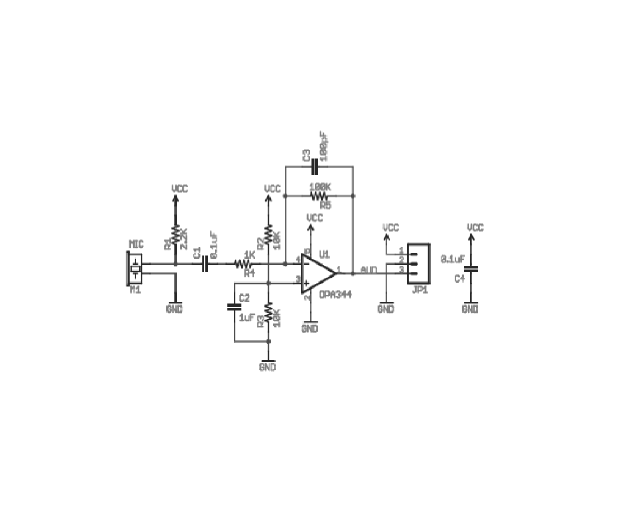
can anyone tell me how deos the circuit attached below works??

i need to know which kind of filters are being used in the circuit?  What is the use of  an RC component at the non inverting terminal of opamp ? Does that RC in the feedback loop make an integrator or differentiator. ? kindly reply at the earlies

  • Hi,

    the circuit forms a microphone preamplifier supplied by a single voltage.

    R2 and R3 are used in this application as simple voltage divider to bias the OPamp to roughly 1/2 Vcc, since the power supply is a single positive voltage and not a symmetrical Dual. C2 shorts noise to gnd and offers a low AC-impedance.

    Other than that the circuit is a classical inverting gain stage with a gain of 100 or +40dB.

    Signal source seems to be a electret or condenser microphone that needs its own power supply feed via  R1. C1 is for DC-blocking purposes.

    R4 and R5 dare the gain setting resistors. C3 serves for bandwidth limiting/stability  purposes. C4 serves as main power supply decoupling.

    regards

    Chris

  • Thanks Christoph Neuhaus . But could you tell me why the non-inverting terminal is to be provided with a voltage Vcc/2 ?? Does the combination R4,C3 &R5 works as an integrator ? If yes how would the output waveform be?

  • Hi, Kiran,

    This is a single-supply circuit, and audio is an AC signal, so you need to bias the circuit at VCC/2 to allow you to get AC swings.

    The cap in the feedback loop acts to reduce gain as frequency increases. You can easily simulate this circuit in our free SPICE simulator, TINA-TI.

    -d2

  • Hi Kumar,

    For reasons that OPA244 has been configured to power by single supply voltage, in order to get the full AC swing amplitude, you need to bias the Op-amp to 1/2VDD to obtain a "virtual ground".

    You can record a sound signal save as .wav file, then importing into Tina-TI to simulate mic-phone inputs to simulate how this circuit works. See my simulation results in below:

    -Jacky

  • Hi,

    neglecting internal OPamps saturation and losses and special types of OPamps, the ultimate voltage limitations for input and output voltages are the power supply potentials.

    As the lower potential is gnd or 0V in this case all of the negative going part of the input signal would simply be cut off. So the signal must be biased so it finds itself within the power supply potentials. Typically a bias point midways between the two potentials is chosen to allow for maximum signal swing and same biasing resistors (cost and ease of design), but need not necessarily be so. It is sufficient that the signal swing remains within the power supply limits (precise: clipping limits of the Opamp).

    R2 and R3 bias the noninverting input to 1/2 Vcc (remark. if the negative supply of the Opamp wouldn´t be 0V but -Vcc the noninverting input would be referenced to 0V, gnd also).  It might help to view the Opamp from a different view as usual. A Opamp always strives to have both of its Difference inputs at the same potential. Any deviation (error) will steer its output such that it drives the associated input via the feedback network to the same potential as the second input. This way the Opamp is viewed as a "failure correcting" or "error correcting" device that minimizes the error signal between its inputs.

    In this case here the noninverting input finds itself at 1/2Vcc. DC-wise there´s R4 between output and inverting input. Only R4 counts, because the invertig input behaves like a virtual ground. Virtual because it isvery  low ohmic, but different to a true gnd it may take up any voltage potential. To drive the inverting input to 1/2Vcc the output needs to take up 1/2Vcc potential also.

    Now  with the output swinging around 1/2Vcc You may need a DC-blocking cap to get rid of this offset if the following device requires a DC-free signal. In that case a 1µ-10µ cap in series with the output, followed by a 100k resistor from output to gnd will suffice.

    With C1=1 µ and C3=100pF bandwidth is limited to ~160Hz - 13.5kHz. C1=10µ and C3=47pF would yield audio bandwidth from 16Hz - 23kHz.

    regards

    Chris