This thread has been locked.

If you have a related question, please click the "Ask a related question" button in the top right corner. The newly created question will be automatically linked to this question.

tas5717 no sound. No errors in register 0x03

Other Parts Discussed in Thread: TAS5717, TAS5717EVM

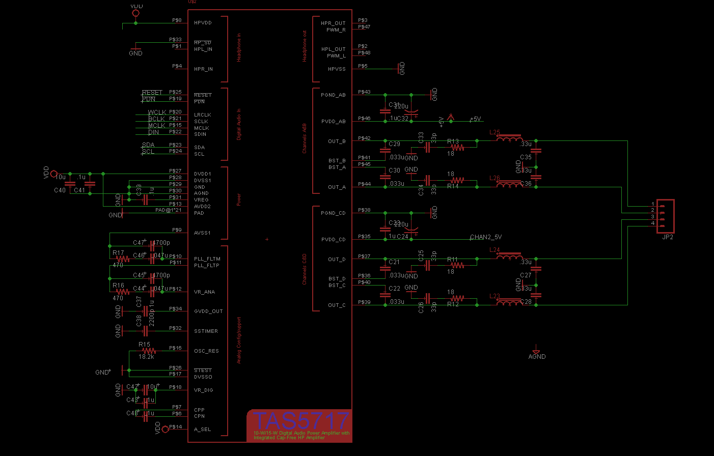
I've wired up a circut containing a 5717 to the mc57xxPISA that came with my tas5717 evk. I can connect over i2c and register 0x00 reads as 0x6c.

I set the ch1 vol 1 and 2 to 1.0 and set the master volume to max using the tas57xx GUI and then unchecked shutdown and mute. On the board provided with the EVK this resulted in audio coming out of the attached speakers. When I tried this on my circuit i got no audio.

The Error register 0x02 is zero. However when i read 0x01 i get 0xc1 (Datasheet says it should be all zeroes) 

Is there anything I'm missing. anything else I should check?

  • Hi Alex:

                 Do you design the Tas5717 board by yourself ?Or it is also from our Tas5717EVK?

                 What do you means about the no audio? Output is nothing? or 50% duty cycle PWM?

                 1. Check whether the power is OK. 

                 2. Check whether I2S signal go into the TAS5717(Clock and Data)

                 3. Could you try to do the following steps using I2C memory tools to see whether it work?

                  write 0x1B     0x00

                  write 0x07(2 bytes)      0x00 30

                  write 0x05     0x00


  • Hi Alex:

                 Do you design the Tas5717 board by yourself ?Or it is also from our Tas5717EVK?

    I've purchased the Tas5717evm and designed my own board based off of the evk. I' neglected to tie the supply and ground pins for the headphone amp to the rails but i wired those connections in with 31 gauge wire.

                 What do you means about the no audio? Output is nothing? or 50% duty cycle PW

    for each amp pair one channel was high and the other was low. they where not changing.

                 1. Check whether the power is OK. 

    Rails look fine. i'm using 5v for my pvcc.

                 2. Check whether I2S signal go into the TAS5717(Clock and Data)

    MCLK, BCLK, WCLK and SDIN are going into their respective pins.

                 3. Could you try to do the following steps using I2C memory tools to see whether it work?

                  write 0x1B     0x00

                  write 0x07(2 bytes)      0x00 30

                  write 0x05     0x00

    After the last write i heard a pop on the speakers. but it's still doing the same thing.

    I'm going to try replacing the chip.

  • Hi Alex:

                  Could you show me your schematic?

                  You said the PVCC is fine, what about the AVDD?

                  Do you configure this part Speaker output?

                   Whether the headphone have output?

  • Here is a Picture of my schematic.

    dvdd and avdd are tied to the same 3.3v rail.

    The variable PWM_OUT is set to Speaker in the tas57xx GUI

    The headphone section is omitted and The hpvdd and hpvss have been tied to 3.3v and ground and HP_SD is grounded.

  • Hi Alex:

                  In our EVM,  pull-up and pull-down the HP_SD and A_SEL have 15K ohms resister. I suggest you use it to make the circuit stable.

                  You said  "for each amp pair one channel was high and the other was low. they where not changing." 

                   Do you means the CHA is High, CHB is LOW, CHC is High and CHD is low? 

                    Whether the current is very big?

                   If you can find some channel is high , I think the part is working already. You will find he output before the inductor should be 50% duty cycle PWM. And after the filter , the output should be PVDD/2 each channel. I think the channel that you test is low have some problem. You can test the output pin from the part to see whether it right. If you can give some screenshot on the scope, it will be better. 

                    Could you make the PVDD a little higher to see whether the part can work normally?

                    You can also try to solder a new chip.

                     By the way, if you use Mc57PSIA connect our Tas5717EVM ,whether our tAS5717EVM can work?  Maybe some problem on the MC57PSIA board configuration.

  • We have a new board with no more edits on it. hpvss and hpvdd connected, HP_SD and A_SEL connected to ground and vcc through 15k resistors.The new board is exhibiting the same symptoms as before. When I bring it out of shutdown in the GUI I hear a pop but it doesn't work.

    I've tried it at a higher PVCC (7.2v) and it doesn't change anything.

    When I connect the MC57xxPISA to the tas5717evm it works fine.

    I've checked out A,B,C and D on the scope on both my board and the EVM. The EVM waveforms are exactly as you describe.

    I've captured the state of channel D and channel C when I try and power up the amp through the GUI.  The first image is D and the second is C.

    Channels A and B just have a small spike and remain low.

    This third image is zoomed in on the first waveform (out D)

    When i observe the startup sequence on the tas5717evm on the same testpoint I see a series of spikes that turn into the square wave over an interval of about 200us

  • Hi Alex:

             The HPVSS pin should connect to GNd through the cap. See the picture below. If you connect the HPVSS to the GND, it will cause short charge pump short to the GND. This is why you start then SD again.


  • Hi, Alex,

    Let me jump in here a second...

    It looks to me like you might be tripping the short-circuit protection.

    The most likely cause for this is a problem with the output filter and load.

    You should have a cap to ground after the inductor, right? Remove those caps, and see if the part starts switching normally. If so, that says your inductor is saturating, and you need to use one with a higher current rating.

    -d2

  • I've added the cap between hpvss and gnd. Lifted the pin and bodged in a 1uf 0201.

    After making this change and attempting to power up the amps (power on, connect via MC57, disable shutdown) i got the following waveform. I attempted to remove the 0.33uf caps to ground after each of the 4 inductors but the waveform on output D didn't change.

    I checked my component values and found the following errors. GVDD_OUT was 0.1uf not 1uf. the cap between cpp and cpn was 0.1uf not 1uf. and the caps to ground  connected through an 18 ohm resistor to out a,b,c and d where 33p not 330p (c25, c26,c34, c33 in my schematic).

    I've replaced everything but the 4 33pf caps and went through the procedure again and got the following waveform on output D.

    would 33pf instead of 330pf me enough to cause the outputs to be unstable? I don't have 330p on hand but I might be able to get 3 100pf caps in paralel.

  • Alex,

    33pF instead of 330pF in the RC-snubber network should not cause an issue 

    Have you checked the four BST-cap's to make sure these are of the right value? A wrong value on these could cause the kind of waveform you captured.

    Do you have another board/device to run a check?

    -Ravi

  • my BST caps are all 0.033u same as in the reference design. Do you think upping them to 0.1u might help?

  • Alex,

    BST should be left at 0.033uF.

    Is this issue seen on multiple boards/devices? -- Have you tried running with the outputs unloaded (i.e. without external load, LC filter, snubber)? 

    -Ravi

  • I have a couple more tas5717s. I could attempt to solder another one on. Do you think having VPVSS tied low might have damaged the device.

  • So, you recommend removing everything except for the boost capacitors? The snubber, inductor, and output cap?

  • Alex,

    You can just try replacing the device first (with filter cap & external load removed)

    -Ravi

  • Replaced the chip with a fresh one. Removed C27, C28,C35,C36. No change.

    Should i assemble a new PCB?

  • Hi Alex:

                How about remove all the output connection just leave the BST cap?

                By the way how do you connect the MC57XXPSIA to your board? Maybe there are something wrong on your connection. Do you have same connector with our EVM?

  • I have testpoints for the i2s bus, i2c, reset, etc..

    I have em wired up using about 4 inches of 31 gauge wire per signal soldered to the testpoints and wire-wrapped onto the MC57

    I'm feeding power directly into the board using a bench top supply.

    The only subsystem populated is the TAs5717.

    MCLK is MCLK, SCLK is BCLK, WCLK is LRCLK, !RST is !RST, !PDN is !PDN, SDIN1 is SDIN1, SDA and SCL are SDA and SCL, VDD comes from the MC57.

    I've checked the signals at the pins of the chip and they're getting through. VCC is a solid 3.297v, and i2c works.

  • Hi Alex:

               Do you connect the two board's GND together?

  • yes, grounds are connected.

  • I've removed the inductors L25 L26 L24 L23 and have attached waveforms for OUT_C and OUT_D. The waveform on OUT_B looks the same as this but there is no waveform on OUT_A.

    My scope is triggering every second or so. it looks like these peaks come in bursts seperated by about a second.

    The next waveform is the waveform on BST_C. IT is identical to BST_D and BST_B. There is no waveform on BST_A

  • Hi Alex:

                You should modify the schematic at the pin9. You should connect the pin to the GND.

                 Please the picture below:

  • Edit made. 

    Re populated board with inductors and caps.
    C&D are at 3.39v
    A&B are at 0v

    Tried with VPP=10v (up from 5v)

    Decided to check the error register (SPI 0x02) noticed the following behavior.

    Power module.
    Read from 0x02 0
    connect through TAS GDE
    read 02 0x80 (mclk error)

    click "shutdown box". Audable click heard.

    Read 02 0x00 (no errors)

    Test with EVM

    0x02 still reads 0x80 before I connect through the GUI but stays stuck (setting that reg to 0 does clear it.)
    Meanwhile, the EVM amp comes up normally and plays audio.


    Trying amps at 10v
    Same behavior, C&D at 3.39v and A&B at 0v

    Swapping another TAS5717 with the TAS5717 on the EVK. (want to verify chip is alive and plays audio)
    Swapped chip, Chip works when mounted on EVK board. Soldered it back onto target board. behavior remains unchanged.

    I think i'm going to check to see if the PCBs are defective. 

    Do you think i should attempt to shorten the cable to the EVK?

  • I've soldered down the A8520E24a91 module and it it is now the source of the i2s data. it's configured to output to a generic DAC. The i2s bus is now 100% on the pcb, no long wires. MCLK,BCLK,LRCLK,Data look fine on the scope.

    I've left the i2c bus connected to the MC57xxPISA and i'm still using the TAS7xx GUI to configure the amp. 

    Nothing changes.

    I've been looking at the schematics and i'm not connecting my HP_SD pin to A_SEL. IS this important? I chose not to because i'm using 0x56 as my i2c address and HP_SD is pulled low.

  • Hi Alex:

               HP_SD pin and  A_SEL is dependent, so not connect together will be fine.

               If you remove the inductance, the output from the pin should be the PWM. When there is no input, the output should be 50% duty cycle.

               It looks like  there is some short circuit on your board. Could you check it?

  • Hi, Alex,

    A very common cause for problems like yours often results in the output filter.

    As Derek suggested above, remove your output filter series element so there is nothing attached to the output pin but the bootstrap cap. Then, as Derek said, you should see a 50% duty cycle there with no input signal, but the device configured to pass audio.

    -d2

  • Make 100% sure your MCLK is accurate. I had an issue with similar symptoms (speakers "pop" on but no audio output). My MCLK was incorrect for the I2S bitrate I was using.

    The board I was using had MCLK tied to a 13MHz oscillator, when I needed  ~12.28MHz. I used an external signal generator to test my theory and it came to life once fed the correct MCLK. Just an idea. 

  • i've removed the output filter inductors and i am seeing a 50% duty cycle PWM. When i unmute the amp and up the volume i can see the same wiggling that i saw on the EVK. It looks like your suggestion was spot on. 

    The values i selected from the output filter where the same as the EVK(15uh and 0.33uf). How should i go about selecting proper values for the output filter?

  • Hi Alex:

                 You can refer this application note for your design.

                 http://www.ti.com/lit/an/sloa119a/sloa119a.pdf

  • Hi, Alex,

    Can you remove the inductors from the EVM and use them on your board?

    Perhaps the current rating of the inductor's you've chosen are not sufficient, or they are not designed for high-frequency switch-mode operation.

    -d2

  • I've pulled the inductors off of the evm and soldered them onto my board. It behaves like it did before. It fails to start. 

    I've checked my boards with a DMM and there appear to be no defects or shorts.

    Looking through SLOA119A i've noticed that the recommended values (table 1) for a BTL LC Filter for AD modulation and a 8 ohm load is 33uH Lbtl and 0.1uF Cand 0.47uF Cbtl.

    The reference design (and mine) used 15uh Lbtl 0.33uf Cg and Cbtl was not populated.  Should I try and use the same component values recommended in SLOA119A?

    Thanks.


  • Hi Alex:

                   I think it will be same if you solder the Cbtl. Do you connect the load? If you don't connect the load, whether it can start up? Could you also check the load is 8ohms?

  • It will not start up with or without the load. The only time i've seen it go is when the inductors where removed. I checked the load with a DMM and it's 8 ohms.

    Could it be a problem with the supply rails? I have 120uF electrolytics and 0.1uF Ceramics on PvddAB and PvddCD but i have the power fed in using 6 inches of 30 gauge wire.

  • Hi Alex:

                  That could be the problem.  I think the wire can not supply enough current to AMP.