


Hi
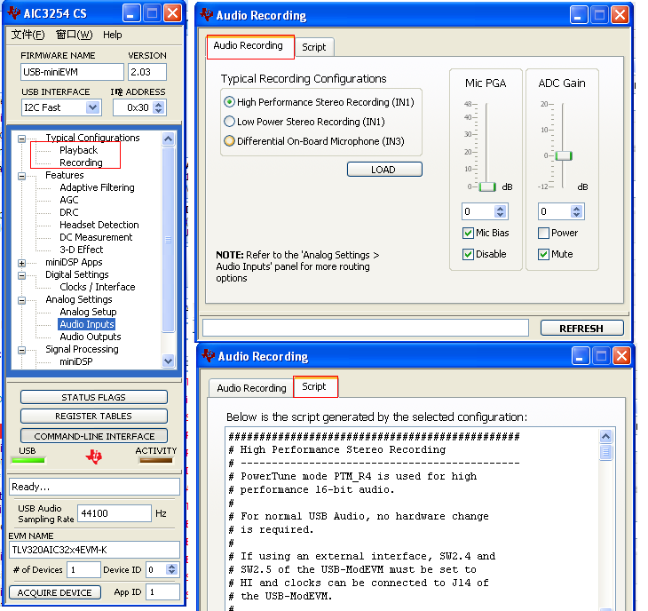
im using aic3204 on a ezDSP C5515 based design board,in the event of trying to capture audio from the codec and feeding that pcm data to speex open source codec

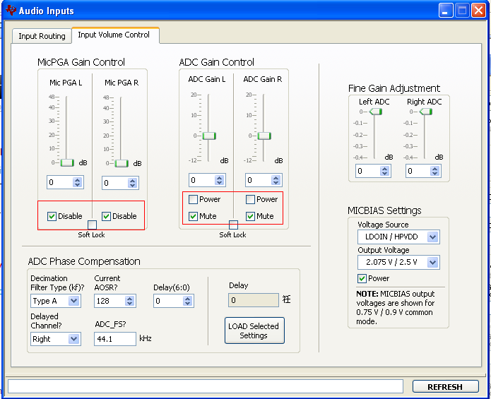
i doubt the codec configurations done i use a electret (2 wired ) micro phone usually it requires mic bias and im using to LDO for that purpose my configuration code as follows
/* ------------------------------------------------------------------------ *
* Configure AIC3204 *
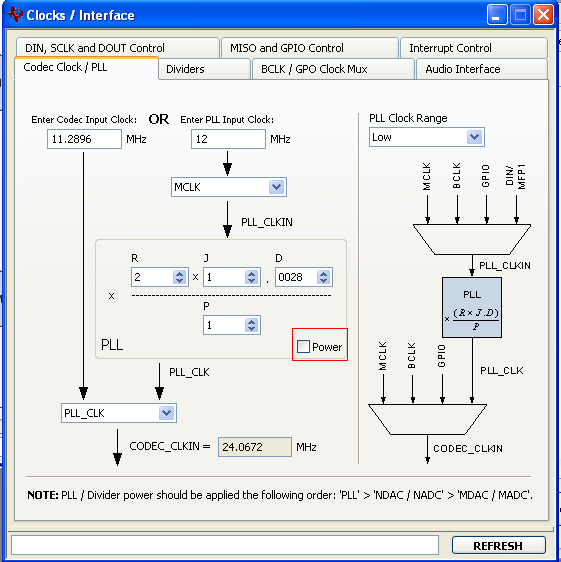
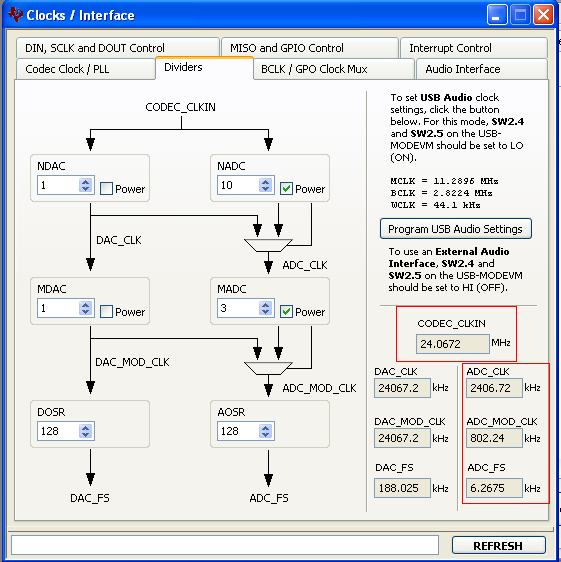
* Set of Values: NADC=10;MADC=3;AOSR=128;R=2;P=1;J=1;D=28; *
* PLL_CLKIN =12Mhz *
* CODEC_CLKIN = PLL CLK=30720000 *
* CODEC_CLKIN = NADC * MADC * AOSR * ADCFS =10*3*128*8000 *
* PLL_CLK = PLL_CLKIN * R * J.D / P = 12000000*2*1.28/1=3072000 *
* PLL_CLKIN = MCLK = 12MHz *
* ADCFS = 8KHz *
* ------------------------------------------------------------------------ */
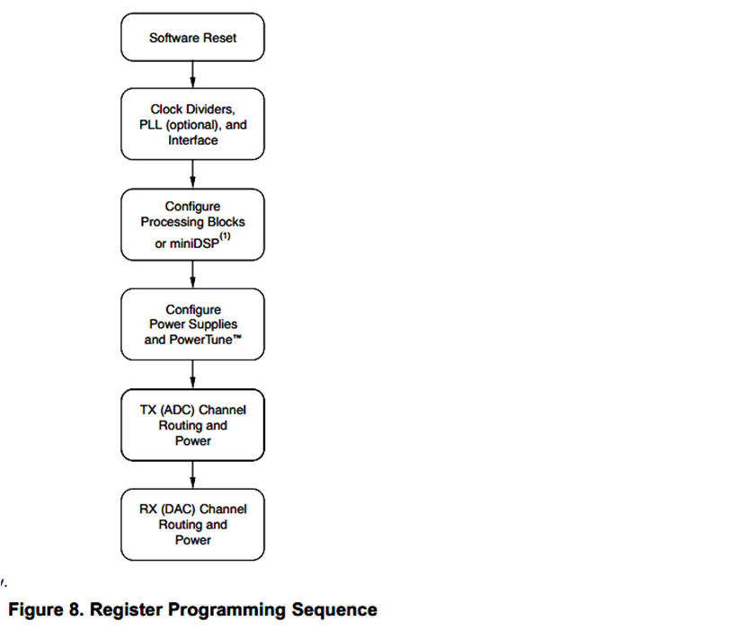
//1.Software Reset
AIC3204_rset( 0, 0 ); // Select page 0
AIC3204_rset( 1, 1 ); // Reset codec
USBSTK5515_wait_Test( 200 ); // Wait
AIC3204_rset( 0, 1 ); // Point to page 1
AIC3204_rset( 1, 8 ); // Disable crude AVDD generation from DVDD
AIC3204_rset( 2, 1 ); // Enable Analog Blocks, use LDO power
// 2.PLL and Clocks Dividers configuration and Power Up For 8KHz Sampling Rate
AIC3204_rset( 0, 0 ); // Select page 0
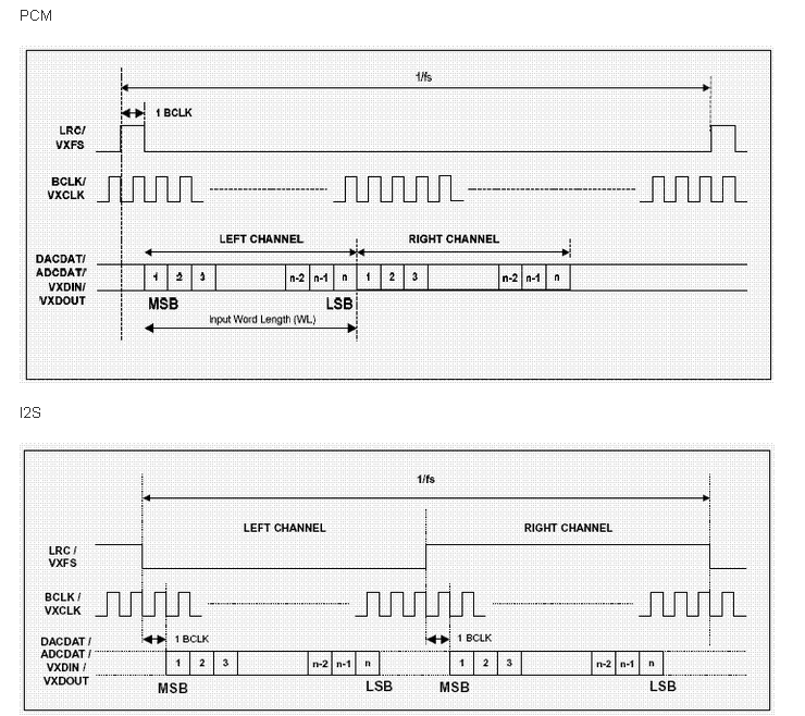
AIC3204_rset( 27, 0x0d ); // I2S interface, 16 Bit, BCLK and WCLK is set as o/p ,DOUT High Impedence
AIC3204_rset( 28, 0x00 ); // Data ofset = 0
AIC3204_rset( 4, 3 ); // PLL setting: PLLCLK <- MCLK, CODEC_CLKIN <-PLL CLK
AIC3204_rset( 6, 1 ); // PLL setting: J = 1
AIC3204_rset( 7, 0x00 ); // PLL setting: HI_BYTE(D)
AIC3204_rset( 8, 0x1c ); // PLL setting: LO_BYTE(D)
//AIC3204_rset( 30, 0x88 ); // BCLK N Divider ->> DAC_CLK/N =(12288000/8) = 1.536MHz = 32*fs
AIC3204_rset( 5, 0x12 ); // PLL setting: Power up PLL, P=1 and R=2
AIC3204_rset( 20, 0x80 ); // AOSR for AOSR = 128 ->> Use with PRB_R1 to PRB_R6, ADC Filter Type A)
AIC3204_rset( 18, 0x8A ); // Power up NADC and set NADC value to 10
AIC3204_rset( 19, 0x83 ); // Power up MADC and set MADC value to 3
//3.Processing Blocks Configuration
AIC3204_rset( 0, 0 ); // Select page 0
AIC3204_rset(61,5); //Select PRB_R5
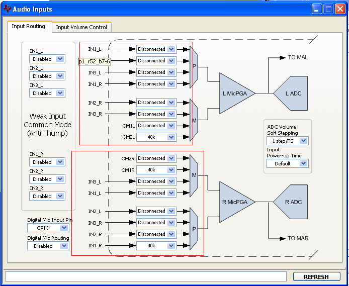
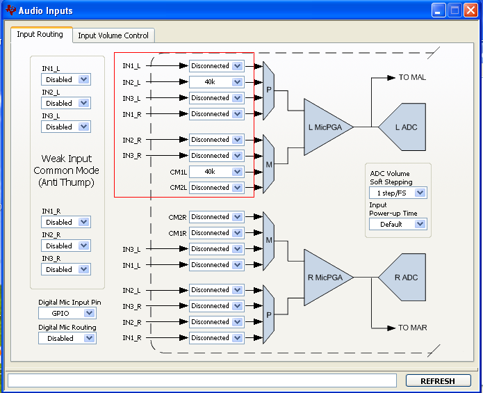
//4.ADC ROUTING and Power Up
AIC3204_rset( 0, 1 ); // Select page 1
AIC3204_rset(10,0x43); //common mode control register
AIC3204_rset(51,0x68); //MicBias = LDO_IN
AIC3204_rset( 55, 0xc0 ); // IN2_R to RADC_P through 40 kohmm
AIC3204_rset( 54, 0x03 ); // CM_1 (common mode) to LADC_M through 40 kohm
AIC3204_rset( 57, 0xc0 ); // CM_1 (common mode) to RADC_M through 40 kohm
AIC3204_rset( 59, 0x5f ); // MIC_PGA_L unmute
AIC3204_rset( 60, 0x5f ); // MIC_PGA_R unmute
AIC3204_rset( 0, 0x00 ); // Select page 0
AIC3204_rset( 81, 0xc0 ); // Powerup Left and Right ADC
AIC3204_rset( 82, 0x00 ); // Unmute Left and Right ADC
AIC3204_rset( 0, 0x00 );
*/
USBSTK5515_wait_Test( 200 ); // Wait
prints("\rCodec Initialization done \n");
/* I2S settings */
I2S2_SRGR = 0x0015;
I2S2_ICMR = 0x0028; // Enable interrupts
I2S2_CR = 0x8012; // 16-bit word, Master, enable I2C
prints("\rI2S Initialization done\n");
Even the Configuration seems OK i am not able to take any valid input data from the codec,if i want to check the loop back how could i do for this configuration, Kindly please resolve my problem.


