This thread has been locked.

If you have a related question, please click the "Ask a related question" button in the top right corner. The newly created question will be automatically linked to this question.

PCM3070 - Audio Mixing configuration

Other Parts Discussed in Thread: PCM3070

Hello,

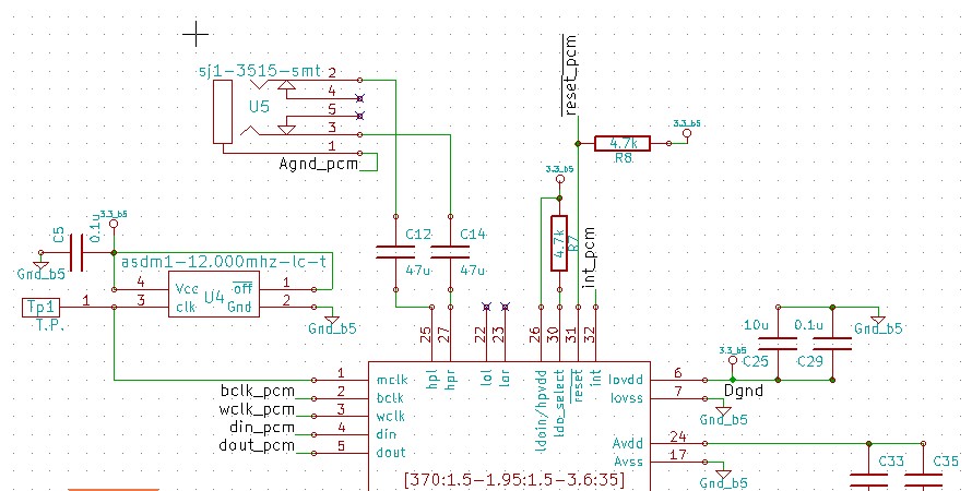
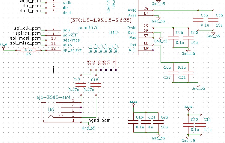
I am planning to implement the below circuit for audio mixing using PCM3070,

Inputs : HPL_A_1, HPL_A_2, HPL_B_1, HPL_B_2

Output : LOR ( pin 23 )

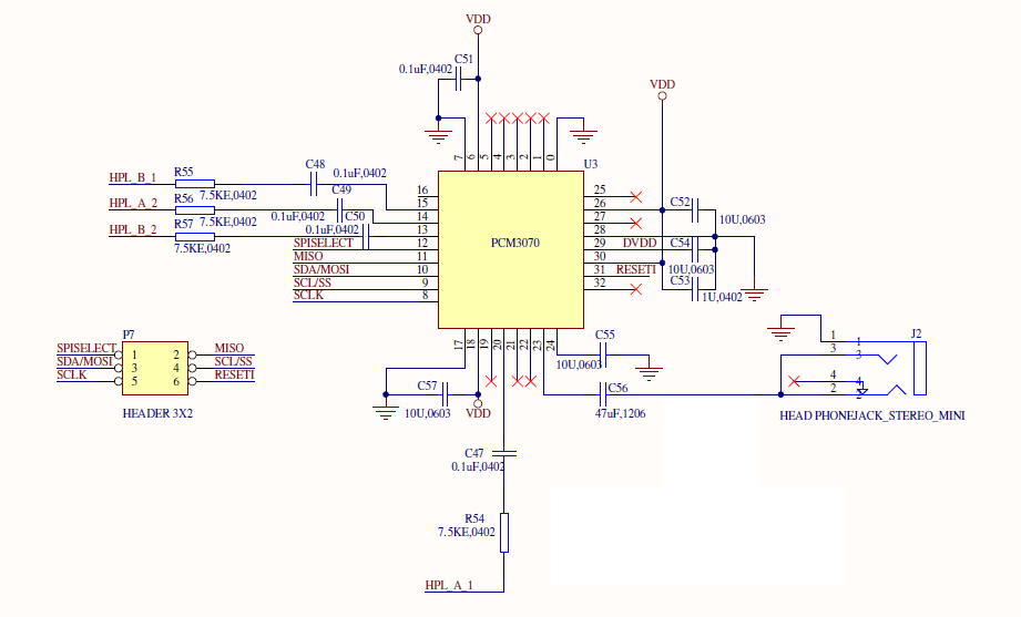
For this, I am trying to configure PCM3070 registers with MSP430 via SPI.

I would like to know what are the registers that are necessary for this application.

I know that its all available in the datasheet, but i would be nice if TI experts could  pin down the necessary registers for this application.

Would be useful for others too.

  • Hi, Winnefred,

    There are some default process flows in the PPS software download. Do you have that?

    -d2

  • Hello Don,

    I have placed a request for the PPS software a week ago, still no feedback from TI,

    Can you please provide me the direct download link for pps, i will look into it.

    Also, In the above schematics, is the voltage supply configuration okay ?

    Kindly check and let me know,

    Thanks,

    Best regards,

    Winnefred K

  • Winnefred,

    There are example configuration settings in this app note: http://www.ti.com/litv/pdf/slaa404c.

    Things to keep an eye for:

    1) An external MCLK is required if using the ADC and DAC converters. I see pin 1 disconnected in the schematic.

    2) Your setup does not use I2S to communicate to other chips. In such case, the BCLK and WCLK must be set as outputs (master mode) if using ADCs and DACs. See app note for an example script.

    3) You setup assumes use of internal ALDO and DLDO. See app note for an example script.

    Regards,

    J-

  • Dear J,

    Thank you for  your reply,


    In my configuration i am not planning to use the ADC and DAC converters. - I believe then it rules out the point 1 and 2, ( attached a pdf that explains the configuration i am trying to achieve via PCM3070 - please let me know if still, i require your recommendation on point 1 & 2 ).

    Regarding point 3, yes, you are right, ALDO and DLDO are my configurations.

    All the example scripts available in the app note are using I2C for communication, is there an example available for SPI configuration ?

    Kindly let me know,

    Thanks & regards,

    Winnefred K

    1651.PCM3070_Analog_diagram.pdf

  • Winnefred,

    Here is an example script for analog stereo PGA bypass. You'd need to modify it for ALDO use and for your specific routings.

    For SPI, ignore the '30'. The second byte is the register value in hex and subsequent bytes are data.

    Regards,

    J-

    ###############################################
    # PGA Analog Bypass
    # ---------------------------------------------
    # This script routes IN1_L/R inputs to HPL/R
    # outputs through MicPGA. Connect a portable
    # media player to J1 (IN1_L/R) and headphones
    # to J9.
    #
    # Ensure the input signal does not exceed the
    # maximum rated input voltage.
    ###############################################


    ###############################################
    # Software Reset
    ###############################################
    #
    # Select Page 0
    w 30 00 00
    #
    # Initialize the device through software reset
    w 30 01 01
    #
    ###############################################


    ###############################################
    # Initialize Codec
    ###############################################
    #
    # Select Page 1
    w 30 00 01
    #
    # Disable weak AVDD in presence of external
    # AVDD supply
    w 30 01 08
    #
    # Enable Master Analog Power Control
    w 30 02 00
    #
    # Set the input powerup time to 3.1ms (for ADC)
    # w 30 47 32
    #
    # Set the REF charging time to 40ms
    w 30 7b 01
    #
    ###############################################


    ###############################################
    # Playback Setup
    ###############################################
    #
    # Select Page 1
    w 30 00 01
    #
    # De-pop
    w 30 14 25
    #
    # Route IN_1L to Left MicPGA P
    w 30 34 40
    w 30 36 40
    #
    # Route IN_1R to Right MicPGA P
    w 30 37 40
    w 30 39 40
    #
    # Mixer Amp -> HP outs
    w 30 0C 02 02
    #
    # Mixer Amp -> Lineouts
    w 30 0E 02 02
    #
    # PGA Bypass Gain = 0dB
    w 30 18 00 00
    #
    # Power up HPL/HPR, LOL/LOR and MAL/MAR drivers
    w 30 09 3F
    #
    # Unmute HPL/HPR driver, 0dB Gain
    w 30 10 00 00
    #
    # Unmute LOL/LOR driver, 0dB Gain
    w 30 12 00 00
    #
    ###############################################

  • Hi Arbona,

    I would like to know the current consumption rating of PCM3070.

    It is not available in the datasheets.

    Also, could you recommend a voltage regulator for the PCM 3070 operation.

  • Hi,

    First, I notice that pin 18 (REF) connection is incorrect. It should only be connected to a cap and not to VDD.

    From power supply perspective, worst case assume 50mA for DVDD LDO + 50mA for AVDD LDO running out of LDOIN supply. On top of that, if you plan to power HP amplifiers out of LDOIN pin directly, then worst case for this is ~250mA assuming 64mW per channel into 16-ohm loads and 50% efficiency of class-AB amps (conservative). So 250+100 = 350mA worst case off 3.3V. In reality, 250mA is typically ok.

    For typical usage without complex miniDSP algorithms, expect ~10mA quiescent when having both ADCs/DACs running.

    Regards,

    J-

  • Hi,

    I have proved your configuration (bypassing adc and dac trougth the pga and mixer amplifier), and it works well. Now I am trying to configure the pcm3070 to input a signal trought the adc and hear that signal from the headphones connected to the dac.

    I have seen the playback examples that appears in pages 67-69 of the slau332 document "pcm3070 Application Reference Guide",  and I have mixed it, I just added the loopback intruccion:

    30 00 00

    30 1d 10  // Stereo adc output is routed to stereo dac input

    But it doesn't work, maybe there is something missing in the configuration, Could you please tell me what is missing?, if neccesary here are the images form the schematic

    Thanks,

    Daniel

  • Daniel,

    Is MCLK, BCLK, WCLK present?

    Regards,

    J-

  • The pin mclk (pin 1) is connected directly to a 12 Mhz oscillator‚ bclk and wclk are not present.

    Thanks‚

    Daniel

  • Daniel,

    For the processing engine to work, BCLK and WCLK must be present either externally or internally. For this case, you would then need to set BCLK and WCLK as outputs. This document describes how to accomplish this in the Appendix section (as sample scripts): http://www.ti.com/lit/pdf/slaa404.

    Regards,

    J-

  • Hi‚

    thank you‚ it works‚ I wasn't aware of that‚ and it was preatty easy to code.

    Daniel

  • Hello all,

    I'm having a similar problem. Could you please post a final configuration of the codec so we can understand how should we do it? PCM3070 without using I2S

    Thank you in advance

    ip