Because of the holidays, TI E2E™ design support forum responses will be delayed from Dec. 25 through Jan. 2. Thank you for your patience.

This thread has been locked.

If you have a related question, please click the "Ask a related question" button in the top right corner. The newly created question will be automatically linked to this question.

Problems with TPA3123D2 amp, stuck in shutdown mode??

Other Parts Discussed in Thread: TPA3123D2

We have developed and fabricated a Circuit Board that uses 4 TPA3123D2  amplifiers to power 8 audio channels. We have begun debugging the board and found that our TPA3123D2  amps at no load are not giving us the correct output. We send a 10k Hz sin wave on the input but only obtain a repeating spike as our output, as if the chip keeps resetting and "popping". This is the only output we can get from our amps, and do not want to plug in our speakers for fear of damaging them.

Furthermore, this output occurs both when the Mute pin is high and low. If we shutdown the amp by pulling shutdown pin to ground, we get no output as expected.

We found a post with a similar problem on here except our problem occurs all the time, and also we do not think it is a layering problem as our board has 6 layers. Our bypass capacitors appear to be fully discharging.  

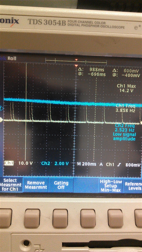
The image below shows  the oscilliscope output , the line in yellow is our output.

We are getting 4 pops every 200ms approximately


Also, We used a 500ohm, 25ohm, and 7ohn resistor as different loads and upon doing that we get no output at all on any of the loads, just a flat line

Any ideas?


  • Hi Steven,

    Can you share your schematic? What happens if you remove the BYPASS cap? I assume all the control pins such as MUTE and SDz have been checked?


    reg,

    Paul.


  • Hi Paul,

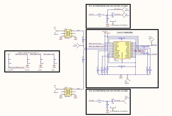
    Thanks for the quick response. Steve and I are working on this issue and I have attached the schematic for your reference. 

    Some quick notes on the schematic:

    - VCC-TPA1 is regulated to 20V by the power supply on the PCB

    - The default states of the TPA control TTL lines were set by pull-up/down resistors

    - C216 and C217 are aluminum electrolytic capacitors

    We haven't tried removing the bypass cap and can certainly try it. One other thing, we notice that the MUTE signal doesn't seem to affect the output which currently just stays flat after placing a resistive load.

  • Hi Steven,

    What is the outputs looks like when the device is powered on. Do you see PWM waveforms at 50% duty cycle at ROUT and LOUT TP-12 (without audio input)? What are the voltages measured on VCLAMP, BYPASS, LIN (TP-13).

    When there is no audio signal or the device is MUTED, the output TP-12 should be a 50% duty cycle PWM waveform.


    reg,

    Paul.


  • Hi Paul,

    Without any load, the output at LOUT and ROUT appears was closer to a 10% duty cycle. This occurs with or without any audio signal present in the input. When a load ( approx < 100 ohms) is inserted, the output at LOUT and ROUT  is essentially a flat line.

    I'll have to double check, but I believe the voltage at the BYPASS pin was around 2.3 volts (with VCC-TPA1 = 20V). The input audio signal was a 10 KHz sine wave with a peak-to-peak voltage of 900 mV (-100 mV to 800 mV). We can check on the voltage at VCLAMP and get back to you. 

    Thanks,

    Lloyd

  • I measured both the VCLAMP and BYPASS terminals, and their voltages are as follows:

    BYPASS:

    2.3V -> Shutdown disabled

    -18.8mV -> Shutdown enabled 

    VCLAMP

    10.6V -> Shutdown disabled/enabled

    Thanks,

    Lloyd

  • Hi Paul,

    A quick update. I removed the bypass capacitor (C214) and I am still getting the same response from the amplifier (~ 10% duty cycle). Any other insight on what could be the problem?

    UPDATE: After investigating a little more, it appears that the IC might be entering into a short circuit protection mode causing it to shutdown approximately once every 200 ms. I looked at previous posts (i.e. [1]) and the problem that we are having appears to be the same. If this is the case, I am not sure what might be triggering shutdown on the IC.

    [1] http://e2e.ti.com/support/amplifiers/audio_amplifiers/f/6/p/160602/588352.aspx#588352

    Thanks,

    Lloyd

  • Hi Lloyd,

    Sorry for the late response. Can you please try removing the capacitors after the LC filter inductors and see if the device can start switching properly at 50% duty cycle PWM without any input signal? I wonder if there is any shorts on the output pins on the PCB board...


    reg,

    Paul.


  • Hi Paul,

    Thanks for the response. I have actually tried removing the capacitor and noticed that the output was now switching at a 50% duty cycle without any input signal. I then replaced the capacitor from 0.22uF to a 1 uF (creating a 50 KHz low-pass filter) and the output remained at 50% duty cycle. With the 1 uF capacitor in place, I was able to apply a 40KHz sine wave to the input of the TPA3123 and it now works like a charm! 

    I'm not sure why the 0.22uF capacitor was triggering a short-circuit protection on the IC on this design which is a 6-layer PCB.  I created a 2-layer PCB of the same circuit but this time left the 0.22uF capacitor in place and we were able to get the amplifier to work.

    Since the final design will have to be on a 6-layer PCB, I will have to play with the filter capacitor value to determine the optimum value needed to maximize my low-pass bandwidth. 

    Lloyd