This thread has been locked.

If you have a related question, please click the "Ask a related question" button in the top right corner. The newly created question will be automatically linked to this question.

AIC32x4: Enabled the H/W AGC and heard the noise on the output audio signal when the input signal is low frequency.

Guru 24520 points

Hi community member,

Would you please provide your comment for this phenomenon?

<Phenomenon>

When applied the following register values for AIC3254EVM-K and input the low frequency (less than 1kHz), the output signal was added the cracking noise.

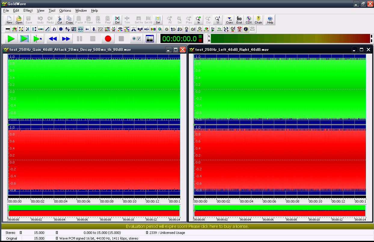
I inserted the waveform to here.

* In this case, I input the 250Hz sine waveform signal to AIC3254(IN1).

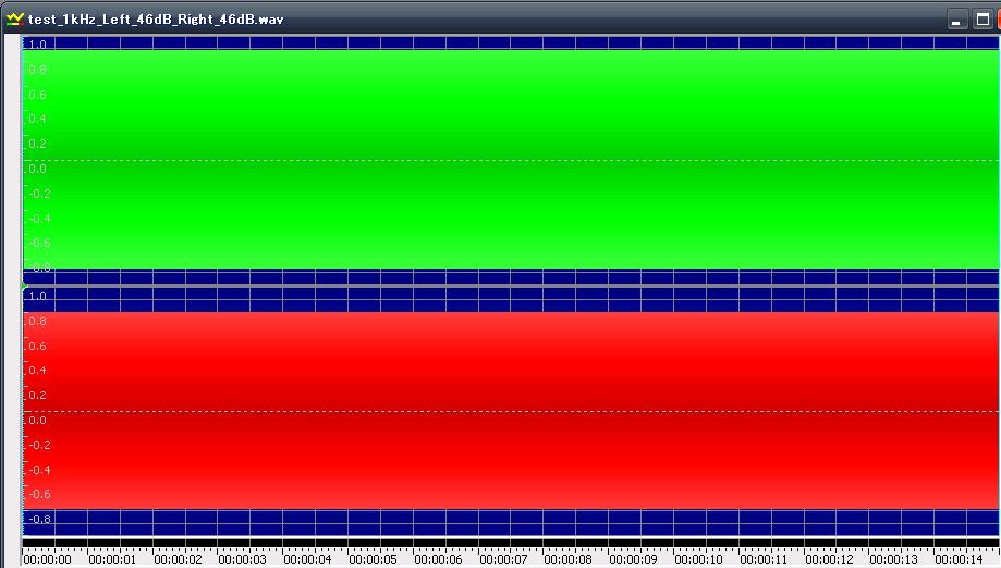
Just in case, I also inserted the 1kHz waveform to here. This waveform did not have any noise.

<Register values>

Apply the "High Performance Stereo Recording" and change the input impedance from 20k to 10k.

#AGC register values

w 30 00 00
w 30 56 83
w 30 57 C2
w 30 58 5C
w 30 59 F1
w 30 5A B9
w 30 5B 06 00
w 30 5E 83
w 30 5F C2
w 30 60 5C
w 30 61 F1
w 30 62 B9
w 30 63 06 00

<Condition>

Fs = 44100Hz

<Note>

1. It seems that when change the max gain value register(Page0, Reg88/96) from 46dB(0x5C) to  20dB (0x28)or 10dB(0x14) or , this phenomenon was improved.

     Of couase, I did not change the input signal level(125Vrms) and frequency(250Hz).  * I attached the  waveform as below.

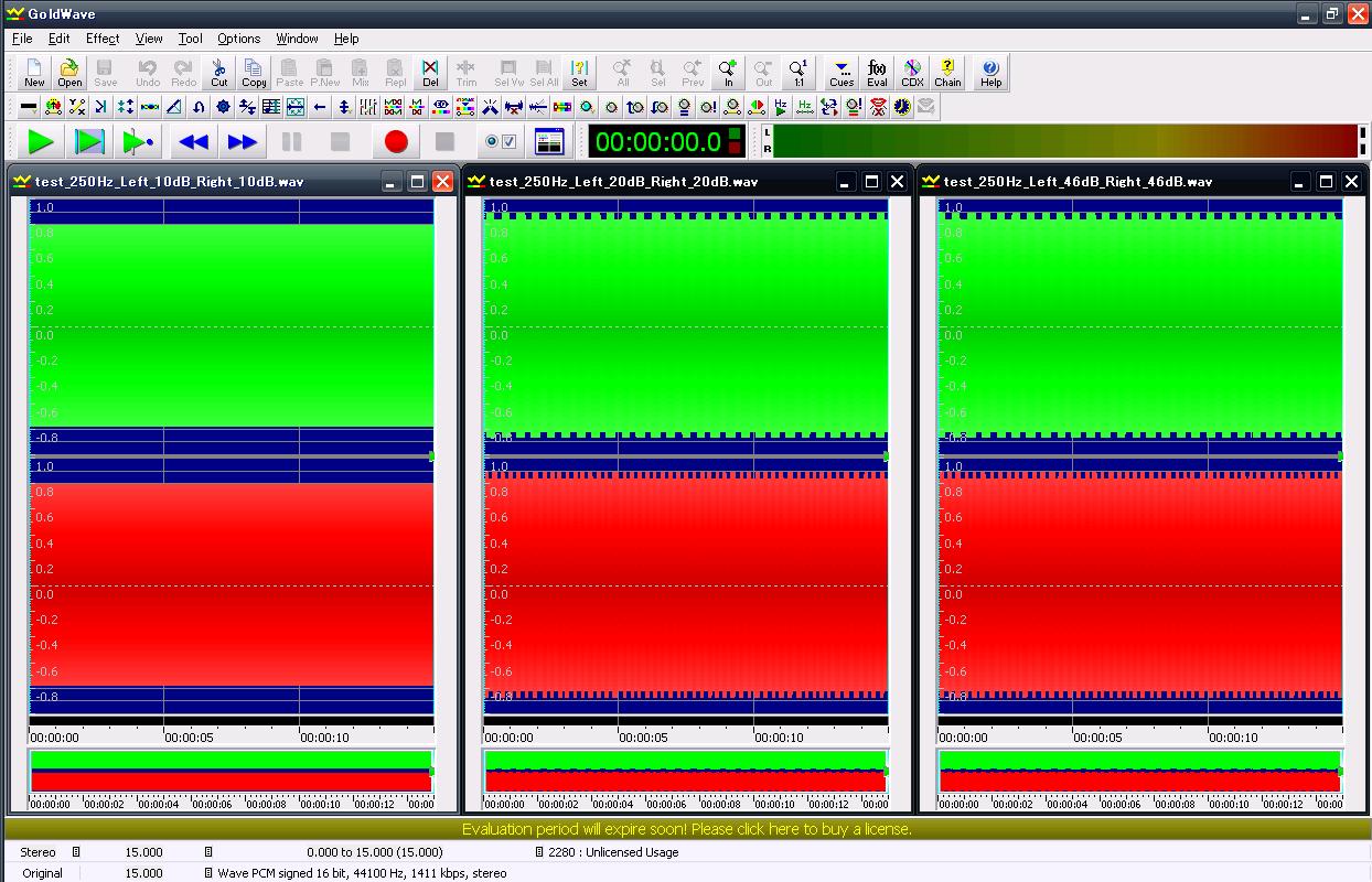
On the left, the max gain value is 0x14. On the middle, it was 0x28. On the right, it was 0x5C.

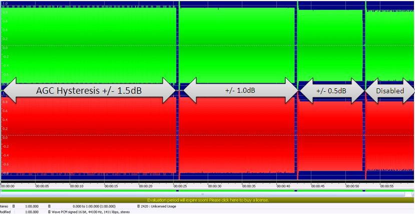
2. In addition to the above, when the decay time was short from approximately 1s to 100ms, this phenomenon was improved.

   I only changed the register of decay time(Page0, Reg90/08) from 0xB9 to 0x19. I also attached the waveform which I recorded.

   * At this time, the MAX gain on AGC was 0x5C.

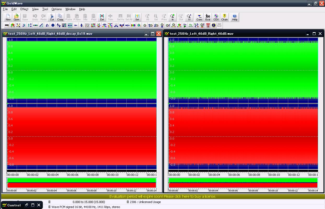
On the left waveform, changed the value of decay time. On the right is the same as "1kHz".

I do not know that why this phenomenon was improved due to change those registers.

So, would you please provide your comments for this?

If you have any questions, please let me know.

Best regards.

Kaka

  • It looks like the AGC oscillates between on and off. Please try changing the noise threshold to -90dB and set the attack time to 20ms and the decay time to 500ms. Detailed explanation for the basic AGC functions is available in http://www.ti.com/litv/pdf/slaa446

  • Hi Hartl,

    Thank you for your response.  I checked the AGC behavior with your suggestion values.  I summarized the result as below. Please check this.

    <Result>

    On the left, used your suggestion values for AIC. * Please see the set registers as below.

    On the right, this is the same waveform as  yesterday's one.

    <Register values>

    w 30 00 00
    w 30 56 83
    w 30 57 FE
    w 30 58 5C
    w 30 59 1A
    w 30 5A A8
    w 30 5B 06 00
    w 30 5E 83
    w 30 5F FE
    w 30 60 5C
    w 30 61 1A
    w 30 62 A8
    w 30 63 06 00

    [Request and Questions]

    I could not improve this phenomenon with using your suggestion values.

    So, would you please re-suggest those values in order to improve it?

    And I have two questions in addition to the above request..

    [Question.1]

    I do not know why this phenomenon will be occurred even though input signal is constant level.

    [Question.2]

    I do not know why this phenomenon will occurred only in cases in which the input signal frequency is low ( less than 1kHz).

    If you have any questions, please let me know.

    Best regards,

    Kaka

  • Hi Hartl,

    Would you please provide your comment for the following phenomenon in addition to the my previous post?

    [Phenomenon]

    When I changed only the AGC Gain Hysteresis values from +/-1.5dB to +/-0.5dB,  it seems that that noise was improved.  In addition to this ,the signal level was reduced approximately 1dB as compared with the value of +/- 1.5dB.

    * I inserted the audio waveform picture as below.  Please check this.

    I do not know what happened due to change this value.

    Best regards,

    Kaka

  • Hi Hartl,

    I have an update for changing the AGC Gain Hysteresis.

    The phenomenon in my experiment , and customer's experiment were different .

    In my previous post , +/- 0.5dB for hysteresis improved the oscillation as you can see.

    However, in the customer experiment, +/- 1.5dB is better than +/- 0.5dB.

    The customer asked the reason why the oscillation happened when the input signal will be low frequency( less than 1kHz).

    If possible, would you please check the operation in you side by using the AIC32x4 EVM?

    Best regards,

    Kaka

  • This oscillation may happen with pure sine-waves (not with an actual signal from a microphone) if the input level of the sine-wave plus the maximum AGC gain exceed -1dB. To avoid this, please reduce the maximum AGC gain so that the total is <= -1dB.

  • Hi Hartl,

    Thank you for your cooperation.  I have an question for setting maximum AGC gain.

    Should customer set the maximum AGC gain change depending on input signal level?

    I could not understand your comments that is "educe the maximum AGC gain so that the total is <= -1dB."

    So if possible, would you please give an example in case with the following?

    Target level: -5.5dB

    Noise threshold: -30dB

    If you need more information in order to give an example of  maximum AGC gain setting value, please let me know the parameters or conditions.

    Best regards,

    Kaka

  • Motoki-san,

    Try to insure that this formula is met when using input sine wave:

     input_level (in dBFS) + max_pga <  target-level +3.9dB

    You can reduce input level or reduce max_pga to reduce the problem. This is only an issue for low frequency sine waves.


  • Hi,

    Thank you for your response.  But I have a question.

     In my understanding, we need to adjust the max_pga or Target-level depending on the input signal level.

    However, how to measure the input signal level in customer application?

    Is there any other workarounds for this issue?

    Best regards.

    Kaka