This thread has been locked.

If you have a related question, please click the "Ask a related question" button in the top right corner. The newly created question will be automatically linked to this question.

LM4675 Inrush Current & Stability Time

Other Parts Discussed in Thread: LM4675, TPA2011D1

Hi,

We have obtained sevral questions from our customers.
When we supply the power supply voltage to LM4675, we found the start-up operation as the attached file of "LM4675_Rush_Current.png".
We seems that inrush current is very large.
How do you think about this?
Moreover, why is it needed 7s as stability time?
Could you please tell us about them?

Best Regards,
Kato

  • Hi,

    We inform you an additional information that obtained by our customer's evaluation.
    When there are not passive devices of output impedance, the inrush current is very small.
    Could you please advise to us about it?

    Best Regards,
    Kato

  • Hi,

    We have obtained one more question from our customers about this inrush current.
    When we change disable to enable by using SHUTDOWN pin, we estimate the inrush current by using the simulator.
    This inrush current is about 1.5A during 20us.
    In consideration of the variation, the inrush current is about 2A.
    In this case, is the short current protection is active?
    Although we already have requested as follows, please tell us the short current protection threshold as soon as possible.

    http://e2e.ti.com/support/amplifiers/audio_amplifiers/f/6/t/273621.aspx

    We think that the inrush current is different by the output impedance.
    If you have your recommended output impedance and the appropriate method of the power-on sequence, please tell us about them.

    Best Regards,
    Kato

  • Hi Kato-san,

    Can you give me device input connection information? If input is open, the device doen't have such long time

    400mA staying and 5sec decay time. I think this comes from input coupling condition.

    Please check input connection.

    Best regards

    T NAOKAWA 


  • Hi Kato-san,

    When you removed output filters from outputs, you don't have much current on the supply

    The reason customer had inrush current will be, if customer applied the signal in single end mode with large coupling cap and other input pin is open or connected

    via small cap to GND. This makes time constant different between +input and -input. As the result, each output avarage DC level will be different. This makes

    looks like inrush current with filter and load condition . But without filter and load, even avarage DC level is different, no current flow between outputs.

    Again please check input connection.

    One thing I want to confirm about why cutomer uses LPF( 10uH & 2nF) on outputs? When customer use real speaker as load, no need to use inductor in sereise.

    10uH is required in only customer takes resistive load because real speaker has inductance element in high freq area. To sumilate speaker load by using

    resitive load, it needs to take inductance.  What is the purpose for the LPF? EMI issue?


    Best regards

    T NAOKAWA  

  • Hi Kato-san,

    I don't think this device has short circuit protection. The device has only thermal shut down protection.

    I still think the reason customer had such big current flow will be inputs time constant different.

    Again please check with customer about input condition.

    Best regards

    T NAOKAWA

  • Hi, Naokawa-san,

    Thank you for your information.
    We will ask condition of input connection and the reason our customers used inductor and capacitor(low pass filter)
    as the output impedance to our customers.
    Then, we have heard that they do not connect to speaker from our customers.
    Just to make sure, we will hear it again.
    Moreover, there is described about short circuit protection on page 1 of data sheet.
    Is this a mistake?

    Best Regards,
    Kato

  • Hi Kato-san,

    Regarding short circuit protection, in the past I confirmed this with SVA audio FAE named Royce Higashi and he said that the device doesn't have short circuit protection

    and only has thermal shutdown protection. He also mentioned that almost all Class-D amps from SVA have only thermal shut down protection.

    Will you confirm with the customer about what is the load? I thought the load is Speaker because of the impedance value was 4 Ohms.

    Best regards

    T NAOKAWA

  •  

    Hi, Naokawa-san,

    Thank you for your information quickly.
    We understood that this device do not have the short circuit protection.
    We have sent an email to our customers just now.
    If we obtain the reply from customers, could you please tell us about them?
    Thank you so much.

    Best Regards,
    Kato

  • Hi Naokawa-san,

    We have obtained the informations of the evaluation and simulation from our customers.
    We remade the evaluation schematic, made the simulation schematic.
    The evaluation schematic is as follow.


    We modified the connection of full differential input and the value of output capacitors.
    Our customers are estimating the parasitic inductor value.
    The device that is connected output load is the structure like as the small speaker.
    This parasitic inductor value would be small.
    This device is something we do not know.


    On the other hand, The simulation schematic is as follow.


    The inrush current flows the output capacitor in this simulation, regardless of output load.


    How do you think about the inrush current and the stability time?
    Could you please advise to us?

    Best Regards,
    Kato

  • Hi, Naokawa-san,

    We have obtained an additional request from our customers.
    Our customers think that if the output pin is shorted, we would like to avoid smokes.
    * The IC destruction resulted from a short circuit of the load.
    We have heard that it was smoke in the evaluation already, it was a problem.
    Is there any recommendation protection circuit?
    For example, we think that we use the poly fuse(about 2A) with a fast response.
    Could you please advise to us about it?

    Best Regards,
    Kato

  • Hi, Kato-san,

    I doubt that a poly fuse will be able to react fast enough. I think it is going to be very difficult to prevent the smoke from appearing.

    It's probably too late, but TPA2011D1 doesn't have smoke when the outputs are shorted.

    -d2

  • Hi, Don-san,

    Thank you for your cooperation.
    We will suggest TPA2011D1 to our customers.
    Thank you so much.
    If we obtain questions from customers, could you please advise to us?

    Best Regards,
    Kato

  • Hi, Kato-san,

    I was on the development team for the TPA2011D1, so, yes, I can answer questions on that device.

    LM4675 was developed by NSC, and I have no idea about it, and no EVM to test it. Sorry!

    -d2

  • Hi Kato-san,

    I just analyzed why inrush current flow when the device gets enable by shutdown control.

    Assuming 2uF cap has no charge at initial condition, Vdd=5V, Inductance value=10uH with ESR=0.25 Ohm Tr=Tf=3 nSec SW priod=3usec  Duty=50%

    With this condition, amplifier outputs start switching from almost 0V to 5V inphase on both outputs.

    For the 1st pulse high level period, the voltage across the inductance is almost 5V because of no charge voltage on 2uF cap.

    In this case the inductor current will increase from 0 amp to about 750mApk/ch, ( dI=(5V/10uH)*1.5us), so both outputs have same amout of current.

    As the total current on the supply will be around 1.5 Amps. and 1st pulse low level period has small discharge from the cap and then 2nd pulse high period will

    pile up the supply current and will reach around 2 amps.  So this is the reason for the inrush current.

    If customer use this kind of LPF on the outputs, every class-D amp will have inrush current flow.

    I have question about inductor and 2uF cap. You said that this indactance is parasitic inductor with 10uH. What kind of routing to 2uF cap from amp output because

    to have 10uH, it will be very long wire or PCB routing.  not real passive indactance correct?

    Regarding 2uF, what is the purpose for this cap? LPF to recover audio signal or to suppress EMI?

    If the load is real 4 ohms speaker, customer doesn't need to put the inductance on the outputs. Customer can connect the speaker directly to amp outputs.

    Only customer needs inductor when customer use resistive load instead of speaker.   Because of speaker has inductance element( about 10 to 15uH) in switching freq range.

    I also confirm I didn't have so long stability time. it was less than 1ms.

    Best regards

    T NAOKAWA

  • Hi, Don-san,

    Thank you for your cooperation.
    We have suggested the TPA2011D1 to our customers, still have not obtained a reply from our customers.
    If we obtain questions about the TPA2011D1 from our customers, could you please advise to us?
    Thank you so much.

    Best Regards,
    Kato

  • Hi, Naokawa-san,

    Thank you for your informations and questions.
    We will read carefully your suggestions later.
    Because we have not obtain a reply from our customers, could you please wait a minute?
    Thank you so much.

    Best Regards,
    Kato

  • Hi, Naokawa-san,

    Thank you for your cooperation.
    We have sevral questions about the stability time.
    If we use real LM4675, the start-up time will become less than 1ms?
    Moreover is there a start-up delay due to heat?
    And, how much is the maximum operating current in the L4675?
    Could you please advise us about it?

    Best Regards,
    Kato

  • Hi Kato-san,

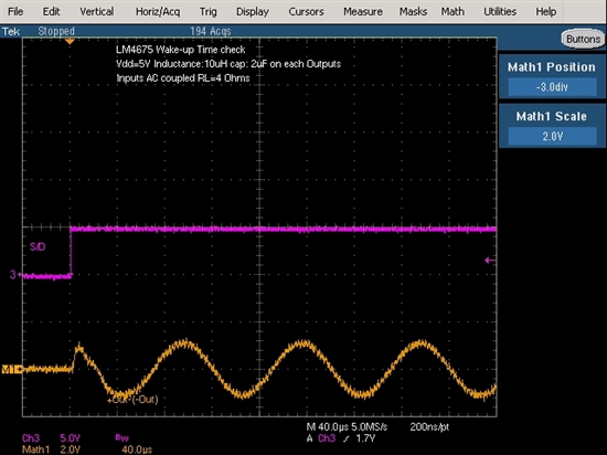
    Yes, the wake-up time from shut down by enabling shutdown control is very fast.

    I just took screen shot and attached it.

    As you can see the screen shot, the wake-up time is very fast and I don't think the wake-up time is affected by heat.

    The value of inrush current on the supply is maximum around 2 amps and it is very short time. The each ch has half of the value which should not be problem.

    The device does not specify max operating current.

    If customer has very long time, it will be better to check input signal settling.

    Best regards

    T NAOKAWA

  • Hi, Naokawa-san,

    Thank you for your information quickly.
    We understood that the wake-up time is very fast, not affected by heat and the inrush current is very short time.
    We will confirm to our customers as follows.
    If the inrush current of 2A is very short time, it is not problem.
    But, this device does not specify the maximum operating current.
    And if the inrush current is very long time, we will hear the input signal settings that our customers used.
    Thank you so much.

    Best Regards,
    Kato

  • Hi Kato-san,

    I like to make a comment on inrush current.  In your response, you will say that "if the inrush current is very long time".  This is not true.

    The inrush current period will be arround couple of switching period. It should not be long. Because inrush current flow to charge 2uF to Vdd/2  from no charge status.

    My geuss for long start up time or wake-up time customer observed is due to long input settling time. Wake-up time on LM4675 is very fast.

    Therefore I suggested to check input signal DC bias settling.

    best regards

    T NAOKAWA 

  • Hi, Naokawa-san,

    Thank you for your suggestion quickly.
    We will confirm input dc bias settings to our customers.
    Thank you so much.

    Best Regards,
    Kato

  • Hi, Naokawa-san,

    Thank you for your cooperation.
    We have obtained a reply from our customers.
    They connected capacitors for full differential input.
    One terminal of these capacitors is connected input resistor, other terminal is connected ground.
    We will meet our customers, discuss about it, feed back the results of the meeting to you.
    Thank you so much.

    Best Regards,
    Kato