This thread has been locked.

If you have a related question, please click the "Ask a related question" button in the top right corner. The newly created question will be automatically linked to this question.

TLV320ADC3101 cannot be muted at single channel correctly

Dear Supporter, 

We found that when we want to set mute to left / right ADC channel by setting the "Page 0 / Reg 82", it cannot be muted correctly.

For example, if we set the right ADC to mute only, it will cause that the left and right ADC channel ALSO be muted. On the other hand, if we set the left ADC channel to mute, it will NOT be mute correctly.

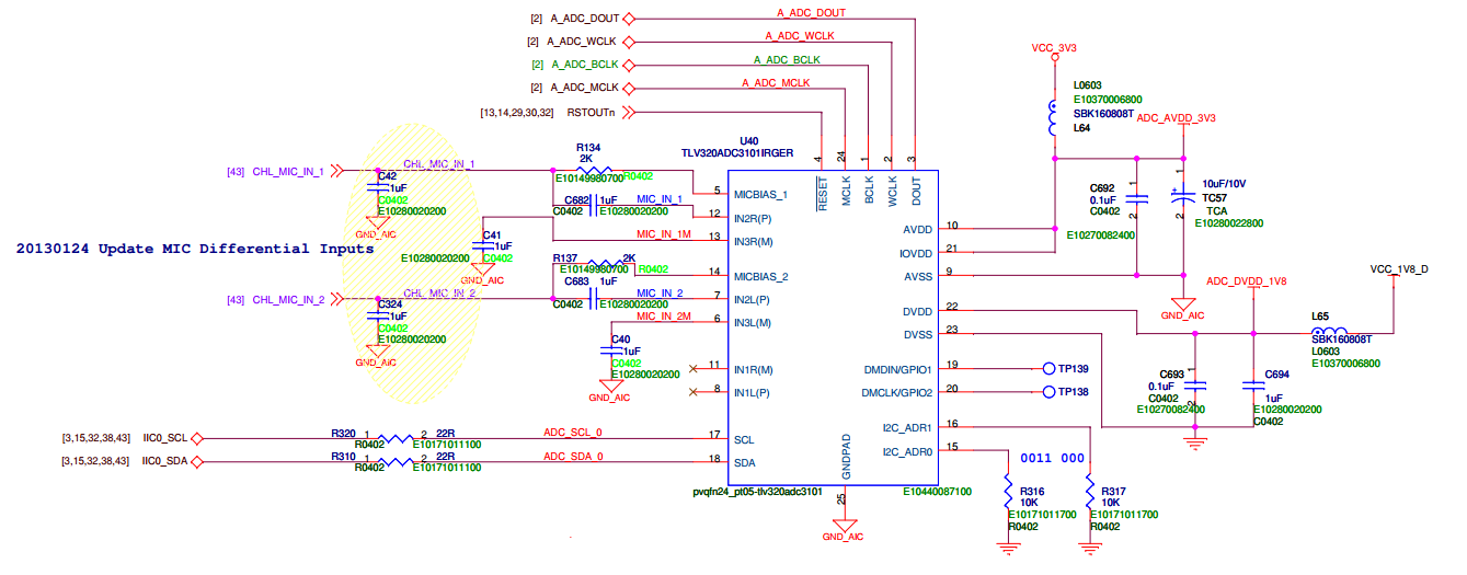
We use the IN2L(P) and IN3L(M) for one pair of differential inputs, and the IN2R(P) and IN3R(M) for another pair at our board. Could you kindly tell us that where should we can modify for our software? Thanks for your helping!

Best Regards,

Steven

  • BTW, we've tested the "Page 1 / Reg 59, 60" for mute, but it's the same as before. It seems like we've controlled the left and right mute via right channel at the same time.

    We use IN2L(P) and IN3L(M) (The IN3L(M) is grounded) to do differential inputs, but we have no idea what cause this reason.

    Thank you so much.

    Steven

  • Hi,

    No inputs should be grounded. This will cause problems. Can you send a schematic and the register sequence you have tried?

  • Dear Supporter,


    We've tried the Single-Ended inputs for IN2L(P) and IN2R(P), but it still has the same situation, too.


    There are our initial sequences as below; in this case, we use the IN2L and IN3L to be the differential pair as left ADC, and use IN2R and IN3R to do another pair for right ADC.


    Page 0, Reg 0, Content = 0x0

    Page 0, Reg 1, Content = 0x1


    Page 0, Reg 0, Content = 0x1

    Page 1, Reg 51, Content = 0x50

    Page 1, Reg 52, Content = 0x2A    // Using IN2L and IN3L

    Page 1, Reg 54, Content = 0x6A

    Page 1, Reg 55, Content = 0x2A    // Using IN2R and IN3R

    Page 1, Reg 57, Content = 0x6A

    Page 1, Reg 59, Content = 0x0       // Left PGA is un-mute

    Page 1, Reg 60, Content = 0x0       // Right PGA is un-mute

    Page 1, Reg 26, Content = 0x22


    Page 1, Reg 0, Content = 0x0

    Page 0, Reg 4, Content = 0x3

    Page 0, Reg 27, Content = 0xC

    Page 0, Reg 28, Content = 0x0

    Page 0, Reg 29, Content = 0xE

    Page 0, Reg 32, Content = 0x0

    Page 0, Reg 81, Content = 0xC2

    Page 0, Reg 82, Content = 0x0       // We do mute here. Set ‘0x80’ for left channel mute, and set ‘0x8’ for right channel mute.

    Page 0, Reg 83, Content = 0x0

    Page 0, Reg 84, Content = 0x0

    Page 0, Reg 5, Content = 0x11

    Page 0, Reg 6, Content = 0x3

    Page 0, Reg 7, Content = 0x0

    Page 0, Reg 8, Content = 0x5E

    Page 0, Reg 18, Content = 0x8

    Page 0, Reg 19, Content = 0x2

    Page 0, Reg 20, Content = 0x80

    Page 0, Reg 30, Content = 0x4

    sleep 1                                             // delay for a while

    Page 0, Reg 5, Content = 0x91

    Page 0, Reg 18, Content = 0x88

    Page 0, Reg 19, Content = 0x82

    Page 0, Reg 30, Content = 0x84


    Please kindly tell us if there are any problems we may change for it. Thank you so much for supporting!


    Best Regards,

    Steven


  • Dear Supporter,

    We’ve read the “page 0, register 36”, and the value is ‘0x44’ that we can make sure the left and right ADC is powered up.


    We also check the HW digital design; it can get the waveform when there are inputs coming by oscilloscope. Please see the attached file, a part of our circuit of ADC3101, to get more information. We wish it may help you, and hope to here your reply!


    Thank you very much!

    Steven

  • We've fine tuned the PLL and register values, now we can solve this issue correctly. 

    Thanks for your helping.


    Regards,

    Steven