This thread has been locked.

If you have a related question, please click the "Ask a related question" button in the top right corner. The newly created question will be automatically linked to this question.

LM4780TA Startup pop

Hello,

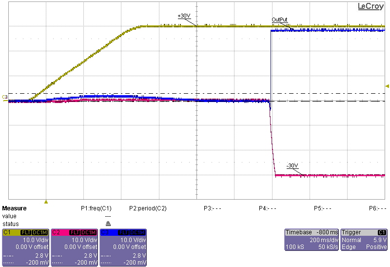
I am using the LM4780 in a bridged configuration to drive a galvo motor and I am experiencing a "pop" on power up which causes the motor to slam into it's stops.  This happens when my -30V supply rail crosses the -9V threshold, at which point, the output of the amplifier is driven to +30V briefly before going back to zero. My mute pins are floating during the power up sequence.  I then tried tying the mute pin directly to ground and I still get +30V on the output momentarily on power up.  What could cause the amplifier to generate an output despite my attemps to force the amplifier into mute mode? 

My power up sequence is +30V rail would come up first, then a second later -30V.     

Thanks in advance.

Best Regards

HV.

  • Hi, HV,

    I believe the answer to your question is in the section of the data sheet titled, "MUTE MODE." It seems MUTE requires -VEE.

    -d2

  • Hi D2,

    Thank you for replying. 

    It seems that I am still a bit confused on this mute pin.  From my understanding, applying -VEE on this mute pin un-mutes the device.  "The switch, when opened or switched to GND, cuts off the current flow from the MUTE pins to −VEE, thus placing the LM4780 into mute mode."  The question is how can this device be enabled, when the mute pin is: 1 -  floating, 2 - physically grounded?

    I appologize in advance if I had mis-interpretted the data sheet.

    HV.

  • Hi, HV,

    I havent personally used this device, but I interpret the d/s to say that the current has to flow into the -VEE pin, and if you -VEE supply isn't up, then the device can't go into mute mode...

    Can you try a bench supply or something where the supplies come up closer together and see if the pop goes away?

    -d2

  • My interpretation from the data sheet is that current flowing from mute pin into -VEE (enables) then device.  Cutting the current flow or grounding the mute pin puts the device in mute mode. 

    To test this, my -VEE is set at -15V and it is connected in series with a 5.9K resistor to the mute pins providing approx 1mA of current per mute pin.  On startup, with the mute pin connected to -VEE, the amplifier outputs is driven to the rails since my processor is not configured yet.  This suggests that it is not muted. 

    Here the mute pin is floating while the supplies are coming up.  Note the "Pop" on the output waveform.

    close up of the "Pop" on the output wave form.

    Here, -VEE (-15V) is applied to the mute pin on startup.  The amplifier gets enabled.

    How can I truly mute the amplifier?

    Best Regards,

    HV.

  • Hi, HV,

    Were these scope shots made with a +/-15V lab supply that comes up with + and - outputs simultaneously?

    -d2

  • Hi D2,

    My appologies I did not explain my test setup correctly.  The +/-30V supplies are on board supplies.  The scope shots above shows the +30V supply coming up and approx a second later the -30V supply.  A -15V bench supply is used to test the mute function.  Applying -15V in series with a 5.9K resistor to the mute pins on startup generated an output as shown above.  Removing the -15V did not generate any outputs but there is the "pop". 

    Best Regards

    HV. 

  • Hi, HV,

    Sorry for the delay; I've been out of the office.

    What I suggest you do is power the amp from a supply that comes up simultaneously to eliminate some variables. My suspicion is the MUTE is not working correctly due to the delay in -VEE supply coming up.

    -d2

  • Hi D2,

    It seems that the mute function depends largely on how the supplies come up.  I've powered my board from an external bench supply and the pop went away.

    My on board supplies can not come up as semetrically as the external bench supply, is there any way to minimize the pop?

    Best Regards

    HV.

  • Hi, HV,

    I'm totally thinking out loud here... But, what if you tied -VEE to ground loosely thru a resistor, and then tied MUTE to ground during power up. I'm not sure if you could find a good trade-off between holding it in MUTE and power dissipation while it's running.

    I suspect the MUTE pin drains some bias current off the base of a transistor, so you just need to provide a path for that current during power-up. I suspect your -VEE is high impedance during start-up, so there is no path for the current.

    I hope that gives you some direction to investigate.

    -d2