Hi everyone:
Recently our company need to develop a class D amplifier and I find this board on TI:
http://www.ti.com.cn/cn/lit/ug/slau508/slau508.pdf
I've got all the chips for this board and tried to build the circuit on our experiment board.
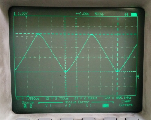
The result is that, when the input signal is a 2 V (Vp-p)sine signal which frequency is 5 kHz, the output (after a RC Low Pass filter) is pretty good, but when the amplitude of the sine signal rises to 4 V (5 kHz), the output is distorted to a triangle wave which amplitude is about 2 V. And I need to reduce the frequency to 2.2 kHz to get a desired output.
According to the paper, this board should work well at 20 kHz when input signal is 4 V. And I built the same circuit as the paper.
So could someone give me advice about this problem?
Thank you.


