


I have several questions about the PCM5102A:
- The chip offers 2 options for the clock input, as stated in the datasheet. Either a 4-wire I2S input (with a system clock) can be used, or the 3-wire "System Clock PLL" mode can be used. The second option does not require a clock signal from the source, and relies on the chip's internal PLL. Which method of connection should be used for maximum sound quality and low jitter?
- When setting options on the chip (such as with the DEMP and FLT pins), is it okay to directly connect the pin to ground for a "low" connection, and directly to the 3.3V supply for a "high" connection? If not, what value resistors should be used (3.3V mode).
- I have noticed that the schematic of the PCM5102 EVM differs slightly from the recommended schematic on the datasheet. The EVM schematic contains what I believe are decoupling electrolyctic caps and ceramic caps on the power supply, while the datasheet only has ceramics.
EVM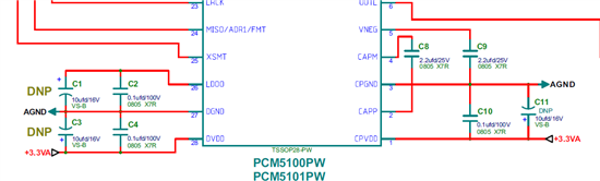 Datasheet
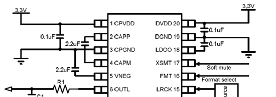
Should I follow the datasheet or EVM implementation?


Thanks.


