This thread has been locked.

If you have a related question, please click the "Ask a related question" button in the top right corner. The newly created question will be automatically linked to this question.

Transformer Design of TPA3116D2 with Transformer Load

Other Parts Discussed in Thread: TPA3116D2

Dear All...

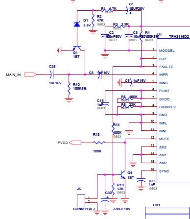
Now my customer is reviewing the transformer design of TPA3116D2 with transformer load. .

Because TPA3116D2 is shut-down by SCP(Short Circuit Protection) when transformer load is applied.

We reviewed the application report of Audio Power Amplifier Operation with Transformer Load.

But we could not find the exact solution of transformer design.

So, We are finding the transformer design solution and want to request your help.

Thanks...

  • JaePhil,

    Please provide a schematic on the connections of the TPA3116D2 to the transformer.  This will help us with a solution.

  • Hi...Gregg Scott

    Thanks for your quick response.

    The schematic on the connection of TPA3116D2 to Transformer is as follows.

    I hope that you give me a transformer design solution for avoiding the saturation of transformer.

    Thanks for your help.

  • JaePhil,

    The connections appear to be correct.  I have some more questions:

    1.  Does the SCP trigger when you connect the transformer primary to the output of the filter?
    2.  Or does the SCP trigger when you connect a load to the secondary of the transformer?
    3.  Is signal needed to trigger the SCP?  If so, what is the amplitude and frequency of the signal?
    4.  Why are you using a transformer?
    5.  What is the final product?  

  • Hi...Gregg Scott

    The answers of your questions are as follows.

    When it is connected the secondary of transformer to load(speaker), TPA3116D2 is shut-down by SCP.

    The FAULTZ pin signal is low (by over current) when TPA3116D2 is shut-down.

    My customer use a transformer for voltage drop compensation due to long connection line between main set and speaker.

    Also, the product of my customer is PA Amplifier for broadcast in school, church, etc.

    Thanks for your help.

  • JaePhil,

    The one question I need answered is the one on the signal level.  This is the audio signal at the output of the amplifier.  I need to know the signal level and the frequency when the SCP triggers.  

    New question:  What is the speaker load and to which terminals on the transformer is it connected?

    I need to know the conditions of the system to understand why it is SCP when a load is connected to the secondary of the transformer.  Since it is AC coupled through the transformer, the SCP must be dependent on the audio signal.

  • Hi, Gregg Scott

    Thanks for your kindly reply.

    Each terminal of transformer is connected to each speaker load as follows. (one by one)

    The 4 terminal of transformer is connected to the 4 ohm speaker load.

    Or the 5 terminal of transformer is connected to the 8 ohm speaker load.

    Or the 6 terminal of transformer is connected to the 125 ohm (total parallel speaker impedance) speaker load.

    Also, the signal level and frequency when SCP triggers, will reply as soon as I have received my customer's data.

    Thanks for your help.

  • Hi...Gregg Scott

    The input and output signal of TPA3116D2 is as follows.

    - Input Signal : 100 mVrms, 50Hz

    - Output Signal : amplified analog signal (50Hz) --> low level by SCP

    The measurement data is as follows.

    Thanks...

  • JaePhil,

    The video was helpful as well as all the information.  This appears to be a system issue.  At 50Hz, the transformer will have more core losses, thus drawing higher current.  This can be tested by changing the test frequency from 50Hz to 500Hz.  Also, measure the current in the output using a current probe this will provide accurate current measurement.  

  • Hi...Gregg Scott

    The test video and test condition is as follows.

    You can see the output waveform and output current of TPA3116D2.

    I think that the transformer is saturated at rapid current consumption point. (Specially, at low frequency bandwidth)

    1. Test condition and test video

        - Input : 50Hz, 100mVrms, Speaker Load : 8 ohm

        - Test Video


    2. Test condition and test video

        - Input : 100Hz, 100mVrms, Speaker Load : 8 ohm

        - Test Video


    Thanks for your help.

  • JaePhil,

    Again, thanks for the videos to see the operation. I see that with the 100Hz present there is some kind of oscillation that occurs at zero crossing and grows with time.  Then the SCP trips at 1.73Arms.  The trip point seems low.  But your meter may not have enough bandwidth to measure the current at high frequencies.   The datasheet states the over current  should trip at 7.5Apk for each channel, so in parallel the SCP should trip at 15Apk if the two channels are sharing correctly.  

    1.  Has the circuit been successfully tested with a speaker directly connected and not through a transformer
          If it has been successful in driving a speaker correctly, then the transformer must not be designed for the system needs.
    2.  Has the circuit been tested at a much higher frequency such as 500Hz or 1kHz?
    3.  Make sure the input pins of the TPA3116D2 are correctly configured for PBTL.  

  • Hi, Gregg Scott

    Thanks for your comments.

    The answers of your questions are as follows.

    1.  Has the circuit been successfully tested with a speaker directly connected and not through a transformer
          If it has been successful in driving a speaker correctly, then the transformer must not be designed for the system needs.

          Answer : It is correctly operated that speaker is directly connected.

                           But it is shut down that speaker is connected through transformer.


    2.  Has the circuit been tested at a much higher frequency such as 500Hz or 1kHz?

          Answer : There is same trouble at 500Hz and 1kHz.


    3.  Make sure the input pins of the TPA3116D2 are correctly configured for PBTL. 

          Answer : The input configuration (single-ended) of TPA3116D2 is correct for PBTL.


    Thanks.

  • JaePhil,

    The setup appears correct.  So the interface with the transformer must be the problem.  I have a few ideas to try.

    1.  Do not parallel the windings on the transformer and try only one primary winding and one secondary winding. 
    2.  You can try the primary windings in series instead of parallel.  The impedance will be mis-matched, but this is for experimenting only.
    3.  What is the part number and manufacturer of the filter inductors?  Send a datasheet if possible.   If these saturate, this can cause this type of behavior.

  • Hi, Gregg Scott

    I have informed your ideas to my customer.

    The part number and manufacturer of inductor is D128-931BS-100M, TOKO.

    The current capacity of inductor is enough for max output power of TPA3116D2.

    The datasheet of inductor is as follows.

    3034.Inductor_D128C-931BS-100M.pdf

    Thanks.