This thread has been locked.

If you have a related question, please click the "Ask a related question" button in the top right corner. The newly created question will be automatically linked to this question.

possible error in PDF

Other Parts Discussed in Thread: PGA2320

Hi: I just downloaded a new reference design for active crossovers.

http://www.ti.com/lit/ug/tidu035/tidu035.pdf

On page 7 the following is written:

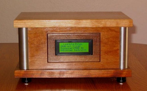
the fourth order Linkwitz Riley filter
has a steep roll off(48dB/octave,80 dB/decade)

I believe that the fourth order rolls off at 24dB/octave...correct?

Regards

Bob C.

  • Hi, Bob,

    I have asked the author to respond.

    -d2

  • Bob,

    You are absolutely correct, my mistake! I will correct the PDF as soon as possible. If you find any other typos, please post them here and I will fix them when I update the PDF. Thanks for checking out my reference design, I hope you find it interesting.

  • Hi John: Thanks for the reply,I really enjoyed your Article,I am an advocate for active filters and you really have come up with a greatly enhanced design,the design equations were also explained with clarity.

    It is too bad that the board is not available to purchase,I may have to build my own prototype!

    Regards

    Bob C.

  • Hi Bob,

    I'm glad you enjoyed the article! I'm a big active filters advocate myself. After messing around with passive crossovers for years it was a breath of fresh air to move to active filters. There's nothing like hitting your desired transfer function on the first try! Those big air core inductors and film capacitors in passive crossovers get expensive too!

    I just took a look around my cube to see if I had any extra PCBs. All the spares I had have parts assembled on them for testing with different corner frequencies and op amps. The easiest way for  you to build a set is to grab the PCB gerber files from the design file are the article's webpage (http://www.ti.com/tool/TIPD134) and submit them to the PCB manufacturer of your choice.

    Good luck!

  • Thanks John: Here is an active x-over(2-way) that I built about 10 years ago,I used digital pots(8 bit) for all frequency determining resistors controlled with a PIC,works really well it was hand wired.....I like yours better !

  • That's awesome! The final product looks really clean, very well done. 

    I'll post my own picture for show-and-tell:

    This is a two way powered loudspeaker using the crossover circuit I detail in that article. The outputs from the crossover circuit go to LM3886s which power each driver directly. I designed the enclosures and then worked with a plastic's company here in Tucson to fabricate 4 of them so we could take pairs to trade shows for demos. 

  • John: I know you from the PE forum,I remember you promised a SOC analog filter chip,Is it finished yet? LOL

    That is a real stunner....You really lit up the forum when you posted that.

    Regards

    Bob C.

  • Ahh yes! I occasionally stop into the PE forum and DIYAudio, I mostly lurk rather than comment but am constantly amazed at how much high-quality audio information is available online now. 

    No SOC yet unfortunately, right now my time is taken up quite a bit with op-amp based audio design which seems to have gotten pretty popular around the world again!

    Thanks for the kind words on the speaker. I have 4 of them right now taking up a huge amount of my desk space here at the office and they are a constant distraction for people walking by!

  • I made this integrated Amp for a company called 4D systems,It uses their 7' inch display and is powered by an arduino Uno,it utilized a PE class D amp,,,Driven with a PGA2320 chip.it was a fun project!

    Robert Cottiers

    more pics here: http://techtalk.parts-express.com/showthread.php?242311-Another-Amp-Case