This thread has been locked.

If you have a related question, please click the "Ask a related question" button in the top right corner. The newly created question will be automatically linked to this question.

TAS5624A Method to Increase Cut-off Frequency

Other Parts Discussed in Thread: TAS5558, TAS5624A, TAS5538, TINA-TI, TAS5548

Hi,

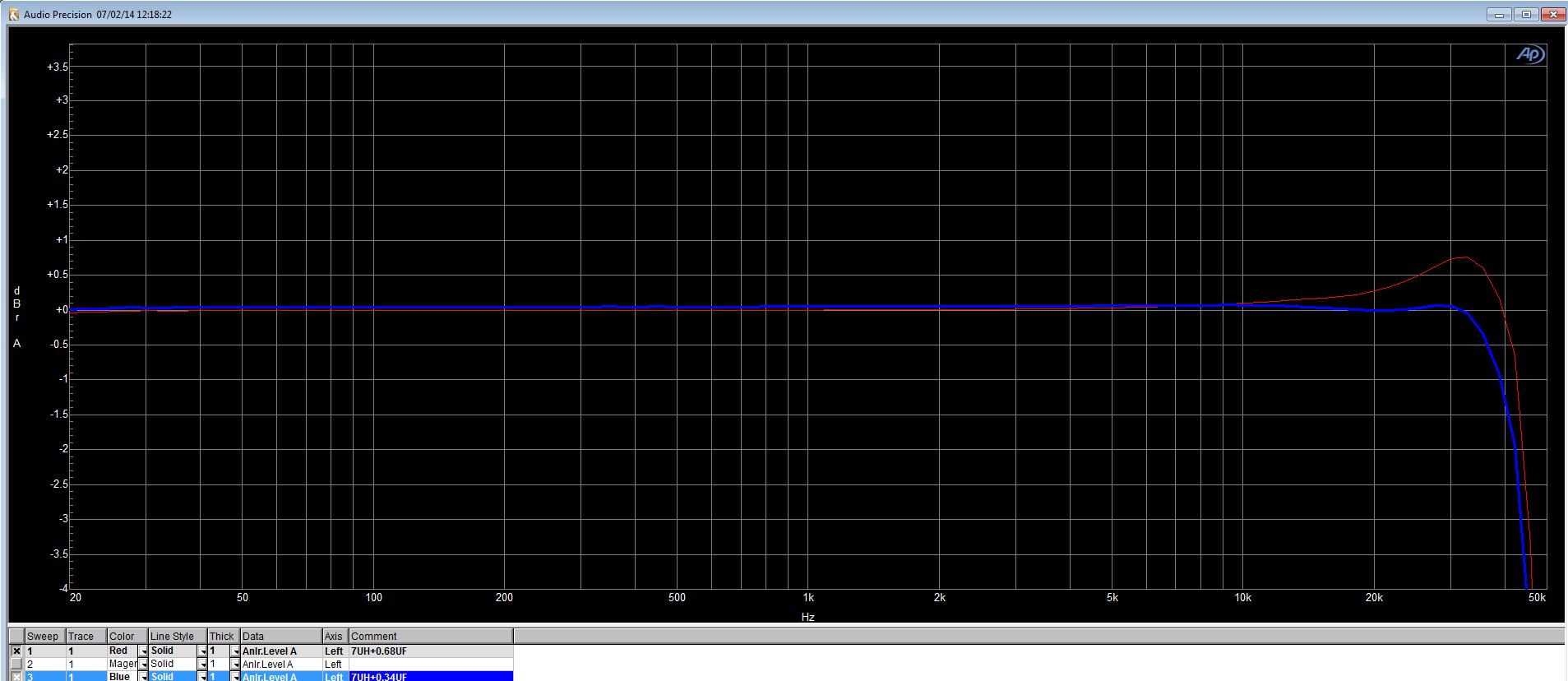
We evaluated the frequency response using TAS5558 and TAS5624A, this result is shown as below.
Since the cut-off frequency is about 36kHz(fs=96kHz), we would like to increase it more.
Could you please tell us how to increase it without changing the external LC filter?

Best Regards,
Kato

  • Hi,Kato,

    Just as we discussed in this post ,we can't increase it ,it's limited by the 1/2fs. You questions shows you have already knowed it well,just ot confirm it again.

    http://e2e.ti.com/support/amplifiers/audio_amplifiers/f/6/p/347745/1234383.aspx#1234383


    Thanks,

    Flora Wang

  • Hi Flora-san,

    Thank you for your reply.
    Although we understand that you can not guarantee a flat frequency response up to 40kHz, could you please tell us as below?
    Is it possible to increase the cut-off frequency up to 40kHz by changing the external LC filter when using 96kHz as the sampling rate?
    In addition, since TAS5538/48/58 are supported 4 channel native audio processing at 192kHz, if the LC filter is changed as well, is the cut-off frequency able to reach over 40kHz?

    Best Regards,
    Kato

  • Hi,Kato,

    it's not possible to change LC filter to increase the cutoff,since the cut off is limited by the 1/2fs fiirst ,and then the cutoff of LC filter.7UH+0.68UF,f0=72.9Khz;

    See here I change the cap by using two 0.68uf series,then the cap nearly comes at 0.34uf,but the cut off still keeps at 40khz.

    By the way,it has already reached 40khz. what's your concern?

    Thanks,

    Flora Wang

  • Hi Flora-san,

    Thank you for your cooperation.
    I understood that the cut-off frequency reaches over 40kHz by using the native audio processing at 192kHz, it depends on the sampling rate rather than the external LC filter mainly when setting 96kHz as the sampling rate.
    Could you please give me your advice if I have any misunderstanding?

    Best Regards,
    Kato

  • Hi,Kato-san,

    You are correct.


    Thanks,

    Flora Wang

  • Hi Flora-san,

    Thank you for confirming my understanding.

    Best Regards,
    Kato

  • Hi Flora-san,

    We have several questions which we obtained from our customer regarding your evaluation condition as below.

    Q1. RC Filter
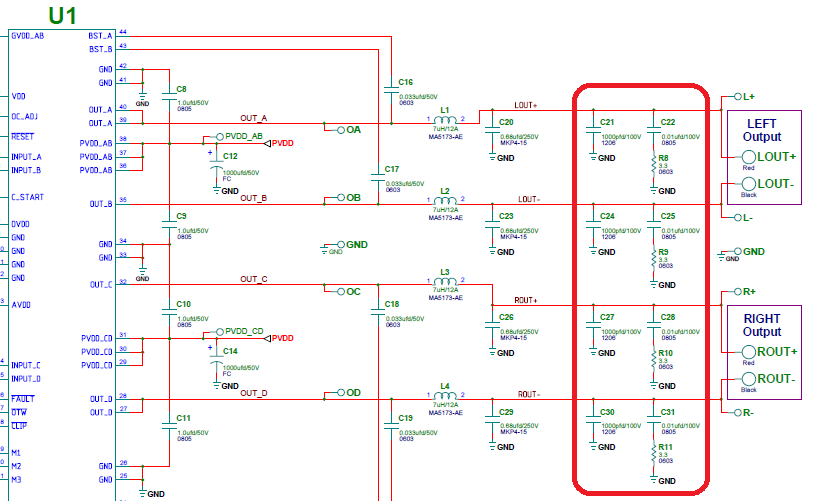
    Did you leave the RC filter connected on the output channels of TAS5624A EVM? (e.g. C21, C22, R8, etc.)
    The schematic of TAS5624A EVM is shown as below.

    Q2. Load Impedance
    Although we believe that you evaluated TAS5624A using 4ohm as the load impedance, could you please tell us the load impedance just in case?

    Q3. AP Filter Settings
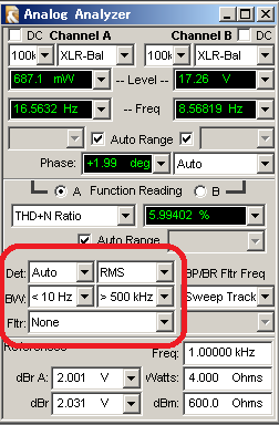
    Could you please tell us the AP filter settings when you evaluated TAS5624A by using the native audio processing at 192kHz?
    The AP filter settings which we used is shown as below.

    Best Regards,
    Kato

  • Hi,Kato-san,

    1.Yes,I don't remove RC filter. The RC filter will work on the high frequency ,it won't impact the 40KHz signal.

    2.I am not 100 percent sure I uesed 4ohms, just maybe.But the load don't impact the cut-off either. The load only have an impact on the Q of the filter.

    3.Yes,my AP setting is the same with yours.


    Thanks,

    Flora Wang

  • Hi Flora-san,

    Thank you for your quick reply.
    I understood Q1 and Q3.
    For Q2, I simulated the external LC filter using TINA-TI as below.
    As a result, I believe that you used 4ohm as the load impedance.

    Best Regards,
    Kato

  • Hi, Kato-san,

    Those RC components at the output are more commonly referred to as a snubber and are used for EMC mitigation. Located after the LC filter, they have very little impact on the THD performance of the amplifier.

    Putting a snubber before the LC filter can help improve THD performance, especially on our open-loop devices.

    -d2

  • Hi Don-san,

    Thank you for explaining so politely.
    I understood it.

    Best Regards,
    Kato

  • Hi Flora-san,

    Could you please tell us which of TAS5538 and TAS5558 was mounted on the board which you evaluated regarding the frequency response?
    We believe that probably it is TAS5558 since TAS5538 does not operate with native 192kHz processing.

    Best Regards,
    Kato

  • Hi,Kato,

    I used TAS5538, TAS5538 192Khz actually operate at 96Khz, so the 1/2fs becomes 48KHZ.

    That's why the cut off is limited at about 40Khz.


    Thanks,

    Flora Wang

  • Hi Flora-san,

    Thank you for confirming.
    I could clear this concern.

    Best Regards,
    Kato

  • Hi Flora-san,

    We have one question.
    Although TAS5548/58 are able to operate the native 192kHz processing for 4channel, are those frequency response same as TAS5538?
    We believe that TAS5538 operates the 96kHz processing, therefore the cut-off frequency of TAS5548/58 is higher than it of TAS5538 when setting the 192kHz processing.
    Could you please give us your advice if we have any misunderstanding?

    Best Regards,
    Kato

  • Hi Kato-san,

    I have tested the TAS5548 and determined that the part, as stated in the datasheet, can perform at 192KHz native processing.

    Regards,

    Justin

  • Hi Justin-san,

    Thank you for your reply.
    Could you please send me the AP screen capture of the frequency response at the native 192kHz processing?
    In addition, could you tell me the measurement procedure of it in detail?

    Best Regards,
    Kato

  • Hi Kato-san,

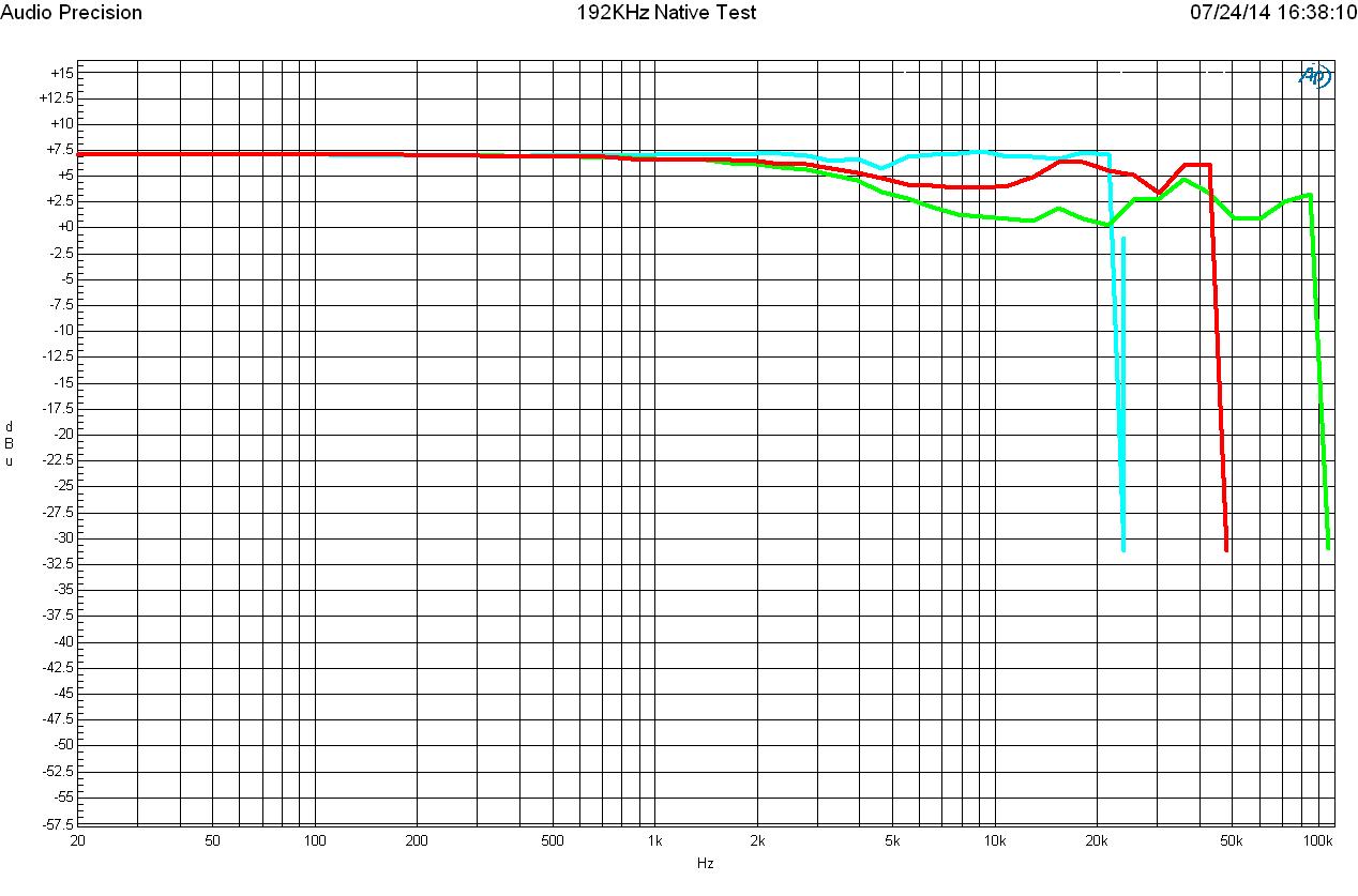
    Below is the capture of the AP output testing 192KHz, 96KHz, and 48KHz, processing. The measurement process included using the default IC register settings (the GUI has its own default register settings that it will write when the program connects to the device, they were not used for this test), from the default registers the following registers need to be changed:

    0x03: change D4 to 0 enable all channels

    0xD9: change the master volume to desired dB, for this test hex value 48, or 0dB was used

    0xC5: change to 00110001, this enables the internal clock for the sampling rate, and enables 192KHz sampling

    In addition to those changes, to verify 192KHz operation, the output filter of the EVM needed to be changed to extend past 100KHz, normally the -3dB cutoff sits around 50KHz. Furthermore, the USB input was bypassed and a 192KHz I2S signal was input straight to the IC with the PSIA.

    I have also attached the test profile for the AP.

    8156.192k_setup.zip

    Regards,

    Justin

  • Hi Justin-san,

    Thank you for your quick response.
    I confirmed the results which you measured regarding TAS5548 and TAS5624A, then I have a few questions as below.

    Q1. the Value of LC Components for the External Filter
    Would you tell me the value of LC components which you used when evaluating?

    Q2. the Degradation of the Cut-off Frequency at 96kHz and 192kHz Processing
    It seems that the cut-off frequency is degraded at 96kHz and 192kHz processing.
    Would you tell me that reason?

    Q3. the Number of steps for the Frequency Sweep
    It seems that the number of steps for the frequency sweep which you set is not a lot.
    That parameter which I have set is 200.
    Is the number of steps which you set enough?

    Best Regards,
    Kato

  • Hi Kato-san,

    Q1: For the external filter I replaced C34 with a 100pf capacitor and replaced C36 and C37 with 15pF capacitors.

    Q2: I do not know the cause of this attenuation, but I can investigate further. This can be fixed with the use of a biquad.

    Q3: The report I posted above was 50 steps, but I re-ran the sweeps at 200 steps and they were almost identical.

    Regards,

    Justin

  • Hi Kato-san,

    Looking further into your questions I realized some things.

    Q1: I did not use an LC filter, but the filter on the TAS5548EVM, which is where my capacitor names cam from.

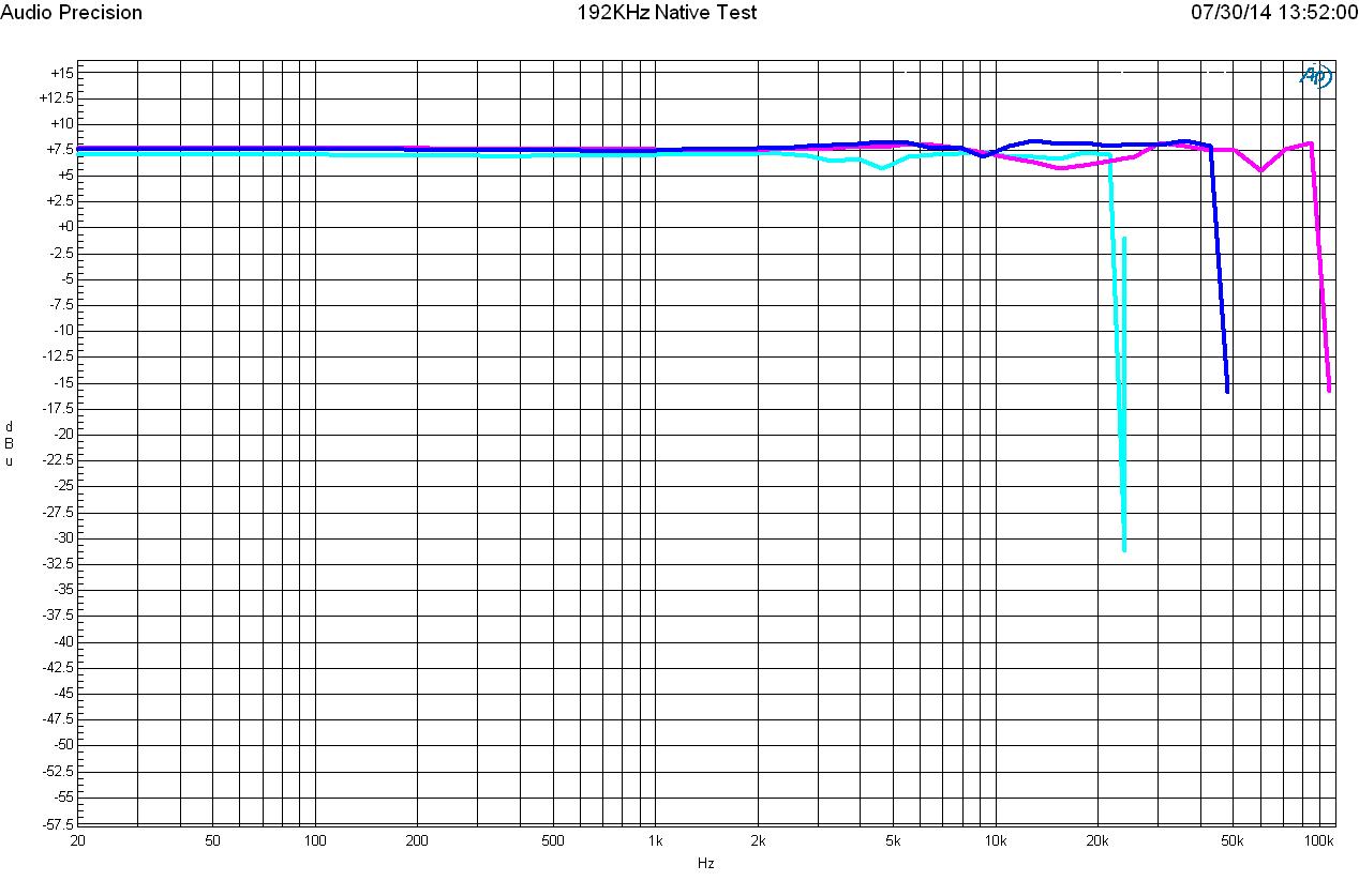
    Q2: I realized that I was measuring the wrong channel (right instead of left, left has the modified filter) so there is no attenuation, I have posted the new sweeps below, with 200 steps each.

    Regards,

    Justin

  • Hi Justin-san,

    Thank you for your cooperation.
    I confirmed Q1, Q2, Q3 and the frequency response.
    For Q1, I understood that you evaluated the headphone outputs(the probing point are the HPL/HPR nodes) when using TAS5548 evm only, TAS5548 has enough performances at 48kHz, 96kHz and 192kHz processing.
    By the way, can TAS5624A bring out enough performances of TAS5548 regarding the high cut-off frequency if connecting TAS5548 to TAS5624A?

    Best Regards,
    Kato

  • Hi Kato-san,

    When using the TAS5624A the datasheet specifies a minimum inductance on the output filter of 5 uH. This limits the output filter depending on the load you use. What load are you planning on using?

    -Justin

  • Hi Justin-san

    Thank you for your reply.
    How much can I decrease the value of capacitor, although I am considering to expand the high cut-off frequency using the constant inductor(e.g. 7uH)?

    Best Regards,
    Kato

  • Hi Kato-san,

    With different loads and what Q you are willing to accept will change what value of capacitor you can use. The limits provided by the datasheet on page 5 are for the inductance (5 uH minimum for TAS5624A) and load resistance minimums. The capacitor value is up to what the application can handle. A good document covering LC filter design is linked below:

    http://www.ti.com/lit/an/sloa119a/sloa119a.pdf?keyMatch=lc%20filter%20class%20d&tisearch=Search-EN

    Let me know if you have any questions.

    -Justin

  • Hi Justin-san,

    Thank you for your reply.
    I understood.

    Best RegarIds,
    Kato