I'm designing a high quality headphone amplifier that should be powered off 12v batteries. The LME49600 was recommended to me, but I don't know if I can use it with a single supply. If I can, can you tell me how?
This thread has been locked.
If you have a related question, please click the "Ask a related question" button in the top right corner. The newly created question will be automatically linked to this question.
Hello.
To get this to work you need to make a virtual ground. Basically, you need to get the ground reference for the circuit to sit in the middle of your battery voltage, 6V in your case. That way the voltage from V+ supply to ground and from V- supply to ground are both 6V and add up to the total 12V supply.
There are a couple of ways to make a virtual ground using voltage regulators or resistors. Search on the web “Virtual ground” and you will find a wealth of information.
The other way to do it is to use two batteries in series with the ground in the middle of the two batteries. That way there is no virtual ground needed since you have a real ground sitting between two equal supply voltages.
Regards
-Matt
I should also mention that TI offers a wide range of headphone amplifier products that run from a true single supply. In this case, the negative side of the battery is ground.
-Matt
Hi Matt,
Thanks for your answer, I'm familiar with the virtual ground concept, and I'm using it on the rest of the circuit.
What I wonder is if the LME49600 would improve and in what what I'm using now, which is an NJM4556.
What other TI products would you suggest that are single supply and can be used off 12 to 15v? What I'm looking should drive 32 to 75ohms pro headphones with very good levels.
It is hard to say if it will be an improvement since audio improvements are subjective. However, The LME49600 has significantly grater current drive capabilities over the NJM4556 part number which is leads me to believe that it might be better at driving a more dynamic load such as a headphone or small speaker. It also has greater slew rate so large output high frequency performance should be significantly shaper sounding and more accurate.
Any of our DIRECTPATH parts are single supply parts that self-generate the negative supply internally. Our TPA6133A2 is a great standalone headphone amplifier that has battery operation in mind. See HERE.
-Matt
Pity the Directpath chips are for lower power supply, and I don't want to use a linear regulator to go down from 12-14v battery.
How do you control level on those chips? I can't use an input pot, because I will be hooking the headphone amp directly at the output of my preamp.
The LME49600 is really a buffer, so I could even connect it to the 4556, if necessary. How do you convert the LME to single supply? On "regular" opamps you connect Vcc/2 to the non-inverting pin, but there's not such a pin on the LME.
The LME49600 has no inverting pin because it doesn’t have a differential input amplifier stage like most op amps. Therefore, you don’t have to worry about it. Just reference the input and output to VCC/2 and all is well!
As for adding an input pot on the headphone amp, I don’t see why you cannot electrically speaking.
Majority of our customers use volume control DACs to drive these and/or some of our headphone amps such as the TPA6130A1 have an I2C volume control with an integrated resistive ladder attenuation network.
Regards,
Matt
This is to be used on a pro and semi-pro portable equipment, and it will be all analog. So no DACs involved.
In fact I'm already loading the output with 10K, so a pot in parallel with that would only demand increasing that resistor a bit, as the variable output would not be seen by it.
I still don't quite understand the principle of using the Vcc/2 reference in input and output, or at least at the output.
The output ground has to be the battery ground, not VCC/2, or I would need a floating output for the headphones, which I don't really want.
To run off of a single battery, the ground must be VCC/2. This is the virtual ground that I discussed earlier.
It is simply creating a voltage tap in the center of your supply so that the op amp V- rail is below the virtual ground and V+ is above the virtual ground. This makes the output of the op amp centered around half of the supply voltage, or 6V if you are using a 12V supply. This is why your output must be referenced to VCC/2
It is exactly the same principle if you had +10 and -10 bipolar supplies, the op amp is centered around 0V (the center point between V- and V+) thus you can reverence everything to 0V or true Earth ground potential.
You are correct, you are floating the output so to speak 6V above true 0V earth ground. It should not be an issue for most things because ground is a relative term.
I can reference a speaker to a 1KV ground and apply 1.001KV on the other terminal. The entire speaker would see it 1V and it would work just fine. It doesn’t care how far it is above earth ground. However if I did earth ground it, then we would have a big problem because we would now have a new reference voltage!
Therefore you cannot tie your virtual ground to the chassis of your enclosure and then tie the chassis to earth ground.
For headphones, you may want the check with the manufacturer if they are active and noise canceling. These may expect to be reference to true 0V earth ground but maybe not.
Regards,
Matt
Well, now I see why TI's paper on single supplies on opamps contradicted the way other audio engineers are using:
http://www.eng.yale.edu/ee-labs/morse/compo/sloa058.pdf
Let's hope everybody gets to some common agreement, but you should know many people only use Vcc/2 for some reference points only, and chassis/battery ground on others. And it does work perfectly alright.
Pity I can't show any schematics here, but it did surprise me why the paper proposed a certain arrangement for a non-inverting single supply opamp, and Walt Jung proposed a different one on his book. Which BTW is the same proposed by THAT on their single supply versions for their products.
I'm not sure if you're aware of that disagreement.
I don't mean your system will not work, but you are really proposing a completely floating system, creating an artificial ground and actually isolating from chassis ground, which I'm not sure works so well for isolating from RFI and other interferences. It's what I wold call "a poor man DC-DC" system.
Keep in mind that not all single supply op amps are the same.
Many single supply op amps provide a negative rail internally using a charge pump so the user can still reference inputs and outputs to 0V earth ground. This is not the same as running a bipolar supply op amp on a single rail.
This could explain some of the discrepancies you are seeing but there are often many means to an end
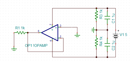
Here is what I would recommend based on what you are trying to do as I think I have a better understanding:
This will float the battery above and below ground instead of the op-amp.
-Matt
The head amp is just part of a whole circuit, where Vcc/2 reference is used on some points, but it doesn't take care of all ground points.
So I wonder if it's still at all possible to use 49600 on such a circuit. Apparently not.
Let me rephrase and try to see how and if it can be done.
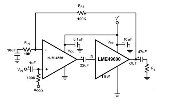
I want to use a two stage head amp with global feedback. On the datasheet there's an LME49710 which I can easy ground the V- pin and reference the nonverting input to Vcc/2. That takes care of the first stage.
How can I do the same with the LME49600 on the second stage?
You can upload images using the little green picture icon in the toolbar and browse from your computer.
Also, have you tried using TI's free TINA TI SPICE software HERE?
You can model your system and simulate to see how your circuit works with the proposed power supply.
I don't know how to use TINA or Spice.
It would be great if someone could simulate my circuit there.
TINA is a graphical drag and drop circuit simulation. If you can draw a circuit on paper, than you can use TINA. There are also lots of tutorials online.
If you draw and simulate and have questions, we can give feedback. I would recommend learning it and trying a few different grounding schemes based on your prior research.
A slight correction on my circuit: there's no more interstage capacitor and the output capacitor is now 100uF.
That would work, but why add the complexity and have more components in your signal path?
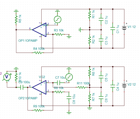
Here are the two options presented. Note that the major difference, that drives all other changes, is where you place the ground. On the negative side of the battery (Bottom) (which is what you proposed), or in the middle of the battery supply voltage (Top).
The top version is superior in my eyes because as I mentioned, you float the battery above and below ground, not the op amp. The battery has no ground reference in this case and doesn’t need one! The output of the op amp is sitting at 0V out at ground becase V+ see 1/2*Vbatt and V- sees -1/2*Vbatt. In the top case you would only need an output cap just to block any DC offset developed in the amplifier from cascading stages together.
In the bottom case, the op-amp is sitting at 6V (+ whatever normal offset develops) because it has to split the supply voltage and are you are referencing the output to ground. The DC output caps and inter-stage caps are necessary between all stages and the input. The entire op amp is floating 6V above ground so all signal inputs and output must be DC blocked with caps.
The final choice is up to you!