This thread has been locked.

If you have a related question, please click the "Ask a related question" button in the top right corner. The newly created question will be automatically linked to this question.

TLV320AIC3106 problem ... sudden connection between ADC and DAC

Other Parts Discussed in Thread: TLV320AIC3106, OMAP-L137

Dear e2e!

We are working with TLV320AIC3106 codec in our own board.
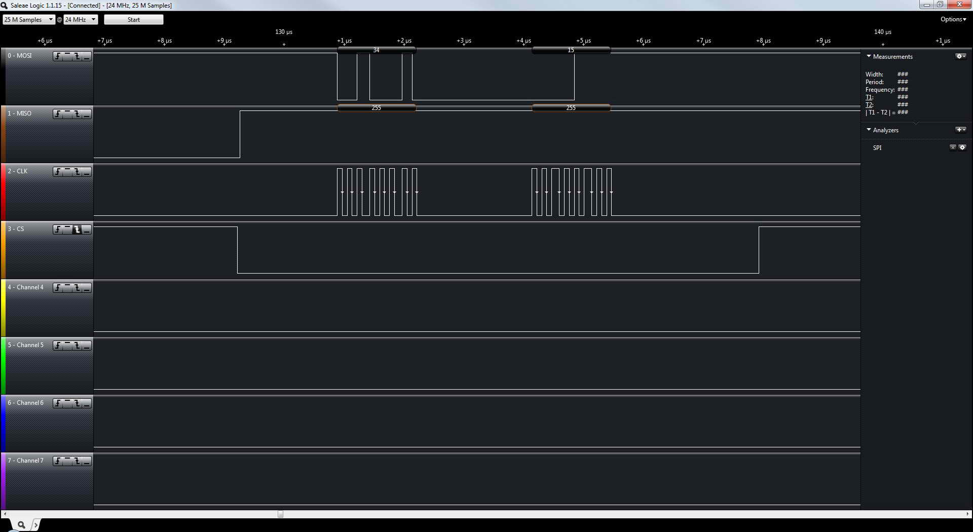
For controlling of the codec SPI interface is used (SCLK=5.4 MHz).
As the digital audio data serial interface the I2S interface is used (SCLK=250 kHz).
To the master clock input (MCLK) is applied a signal with 2.066 MHz.

We need to make numerous reconfiguration of codec during its work  (under "reconfiguration" I mean changing PGA gain or connection/disconnection of analog inputs from PGA or analog outputs from DACs).

For example, we send periodically two blocks of commands to the codec:

< First block >
1) connect MIC3L to the left ADC (Reg17 = 0x0f);
2) disconnect DAC_L1 from LEFT_LOP/M (Reg82 = 0x7F);
3) disconnect DAC_R1 from LEFT_LOP/M (Reg85 = 0x7F);

< Second block >
1) disconnect MIC3L from the left ADC (Reg17 = 0xff);
2) connect DAC_L1 to LEFT_LOP/M (Reg82 = 0x80);
3) connect DAC_R1 to LEFT_LOP/M (Reg85 = 0x80);

Period between sending of each block of commands: few seconds and more.
Each reconfiguration command is sent to the codec via SPI interface. Format of the command: < number of a control register >,  < data to be set >,  < 10us pause >,  < number of next control register > ...  etc.

The problem is, that after sending of several of such blocks of commands (from 10 to 100)  codec begins to transfer data from ADC directly to LEFT_LOP/M output (through DAC). So after we send first block of commands (connect MIC3L to the left ADC  and disconnect DAC_L1/R1 from LEFT_LOP/M ) we HEAR A SIGNAL FROM MIC3L IN THE LEFT_LOP/M OUTPUTS !!!

It is seems, that the signal is transfered directly through ADC an DAC of codec ... through SW-D1 of codec (see "simplified block diagram" on datasheet SLAS509E).
But we can't control this switch directly...

We have tried:
1) to read back the control registers of the codec after the beginning of this parasite transfer. Registers 80...85 are equal to 0x00. LEFT_LOP/M seems to be disconnected, but, in the real world, signal from MIC3L is transfered to the LEFT_LOP/M;
2) to powerdown the DACs (Reg37=0x00). This transfer is dissapeared! But it isn't a solution, because we plan to use these DACs for translating of a external signal, that comes from a external CPU via I2S interface;
3) to disconnect DIN, DOUT and BCLK pins of codec from external CPU. Doesn't help. Parasite transfer is steel exist.

We would be very appreciate for any help and suggestions about this issue. For our purposes we need two independed ADC and DAC channels, which could be connected or disconnected to the input or output amplifiers of a codec. 
May be there is some ERRATA on TLV320AIC3106, which describes some similar problems....

With many thanks in advance!
Vitalii

  • Hello Vitalii,

    Thank you for bringing this to our attention. I'll take a look at this in more depth and get back to you ASAP.

    Please let me know if you need anything else,

    Nate

  • Hello Vitalii,

    After looking into this a little more, I have seen something similar with this same device. Let's look at a couple options:

    1) Do you have access to a protocol analyzer? We typically use this one: http://www.totalphase.com/products/beagle-i2cspi/ but it doesn't matter which one you use. It would be really helpful if you could check your SPI lines and make sure you are writing what you expect. The previous case I had with this part, the engineer was doing some unintentional writes due to some software bug. He ended up with a very similar issue, and the audio team runs into this quite often.

    2) Could you also double check your routing settings? there are multiple ways for the MIC3L to get to LEFT_LOP, particularly through DAC_L3, or even bypassing the DAC through PGA_L (Register 81).

    It's also worth mentioning, the block diagrams show many of the outputs as being muxed, but they are in fact simply connected together, so it's important to completly disconnect and not send multiple signals to the same outputs unless you want them to mix.

    3) Finally, does this issue recreate itself on an EVM? this would help isolate the issue.

    Please let me know the results of these tests,

    Nate

  • Dear Nate!

    Thank You very much for your answer!

    1) Yes, we have a logic analyser and we will to check our SPI interface. 
    But note please, this problem appears after series of successful commands to the codec. I hope, we will catch all SPI commands directly before the appearing of the  problem;
    2) Where is DAC_L3 in the TLV320AIC3106 codec? I see only two DACs (DAC_L and DAC_R). Yes, we have checked registers from 80 to 85 (multiple ways for the MIC3L to get to LEFT_LOP). They all are set to the 0x00 or 0x7f (are not routed to LEFT_LOP/M);
    3) TLV320AIC3106 EVM ... unfortunately we haven't such board.... We have only OMAP-L137 EVM with this codec. In principle, we can try to recreate this problem at this board.

    I will report you about results of tests.
    Regards,
    Vitalii

  • My pleasure! I look forward to seeing the results of your test.

    To answer your question about DAC_L3, you are correct that there are only two dacs, one left and one right. The DAC_L3 refers to which line the dac is being output to. This is controlled by register 41 on page 0. DAC_L3 feeds from DACL directly into LEFT_LOP. This is different from, for example, DAC_L1 which goes into a volume control mixer (controlled by R82 page 0) before it goes to LEFT_LOP.

    Hope this helps!

    Nate

  • Hello Nate!

    Thank You for explanation! We have checked. Reg 41 is equal to 0. So, probably, signal goes into a volume control mixer (controlled by R82 page 0) before it goes to LEFT_LOP.

    We have tried:

    1) before and after problem we have read back all values, which are stored in the control registers of the codec (see please listing below). ... Values are identical and corresponds to the desired configuration of the codec. (I mean "desired" - without this parasite transfer ...);

    2) we have checked SPI interface with the codec (see please pictures below).
    Our analyser displays near a same picture, as is shown at the figure 14 and figure 15 (SPI write/read) of the datasheet. BUT! There is a pause between command and data words. During this pause SCLK pulses are not generated. Can this pause  cause problems? ... after more than 100 of successful writes ....

    We will be very appreciate for any suggestions!

    Regards,
    Vitalii

    --------------------------
    SPI interface control and data words  (from logic analyser)

    ---------------------------
    What we have read back from registers of the codec
    RegNo  Value (HEX)
    0           0
    1           0
    2           0
    3           10
    4           4
    5           0
    6           0
    7           8a
    8           0
    9           c0
    10           0
    11           a1
    12           fa
    13           0
    14           0
    15           50
    16           14
    17           0f
    18           f0
    19           fc
    20           78
    21           78
    22           7c
    23           78
    24           f8
    25           86
    26           31
    27           80
    28           2a
    29           0c
    30           80
    31           2a
    32           0
    33           0
    34           c2
    35           c2
    36           cc
    37           c0
    38           10
    39           0
    40           0
    41           0
    42           0
    43           0
    44           14
    45           0
    46           80
    47           80
    48           0
    49           80
    50           80
    51           0f
    52           0
    53           80
    54           80
    55           0
    56           80
    57           80
    58           0f
    59           0
    60           0
    61           0
    62           0
    63           0
    64           80
    65           0f
    66           0
    67           0
    68           0
    69           0
    70           0
    71           0
    72           4
    73           0
    74           0
    75           0
    76           0
    77           0
    78           0
    79           0
    80           0
    81           0
    82           7f
    83           7f
    84           0
    85           7f
    86           0b
    87           0
    88           0
    89           0
    90           0
    91           0
    92           0
    93           0b
    94           de
    95           8
    96           0
    97           0
    98           0
    99           0
    100           0
    101           0
    102           2
    103           0
    104           90
    105           0
    106           90
    107           c0
    108           0
    109           0
    110           0
    111           0
    112           0
    113           0
    114           0
    115           0
    116           0
    117           0
    118           0
    119           0
    120           0
    121           0
    122           0
    123           0
    124           0
    125           0
    126           0
    127           0


  • Hello Vitalii,

    Thank you for the extra data. This is extremely useful. From your tests the most likely cause of the issue would be the routing. These devices sometimes will have routing errors if not done in a standard sequence. When changing your routing (for example disconnecting and connecting DAC_R1 to LEFT_LOP/M) we recommend to go through the entire DAC and route all the way to the output to connect and then unroute the entire change before routing something else.

    For example, to route DAC_L1 to LEFT_LOP, first unmute volume control, power up the dac, route DACL1 to LEFT_LOP, then power up the output stage and then unmute the output stage.

    To disconnect, then do the opposite commands in reverse order. So mute the output stage, power down the output stage, unroute DACL1 to LEFT_LOP, power down the DAC, mute the volume control.

    To switch routing on the fly we suggest to completely disconnect and then completely reconnect to avoid any sporadic issues. As simply toggling the routing of DAC_L1 to LEFT_LOP could cause issues.

    The same applies with routing to the ADC.

    In regards to the SPI, the pre and post error memory dump was very helpful. The fact that they are both as expected shows that you are getting good writes. Operating outside of the datasheet always runs the risk of unexpected behavior, but because your writes are good this is likely not causing the issue you are seeing. I still recommend removing the pause if possible to make sure the SPI writes are as robust as possible.

    Please let me know if you would like any additional clarification, or if this does not solve your problem,

    Nate

  • Dear Nate!

    Thank You very much for reply!
    We will try to apply the "standard sequence" during changing our routing.
    And then, I hope, we discuss the results together!

    For the interfacing with codec via SPI we use 8bit-ATMega2561.
    Unfortunately, it seems to be impossible to completely remove the pauses between  SPI writes in this Atmel processor.

    Regards,
    Vitalii

  • Dear Nate!

    1. We have applied the advised sequence of the commands for changing the signal route in the codec. Now we trying to turn the codec into erroneous mode. But, till now, it is unsuccessfully :-). We will try to do this tomorrow ... it is so incredible.... :-)

    2. What we need do for powering down the output stage ("output stage" is LEFT_LOP/M )?
    There is Reg 86. As described in datasheet SLAS509E this register has D0 bit ("LEFT_LOP/M power status"). It is marked as Read-only. BUT. The similar register for HPROUT (Reg65) has the same structure, but its bit D0 is marked as R/W.
    Can we power off LEFT_LOP/M by writing the D0 bit in the Reg 86 (can we assume, that D0 is R/W instead R)?

    3. Could you please to confirm the correctness of command sequence for changing  routing in the next cases:
    a) turning on the signal route "Mic3L- Left PGA - Left ADC":
         
          // unmute left ADC PGA
          tempReg = codec.get(15);
          codec.set(15,tempReg & 0x7f);

          // power on left ADC
          tempReg = codec.get(19);
          codec.set(19,tempReg | 0x04);

          // connect (route) MIC3L to the left ADC
          tempReg = codec.get(17);
          codec.set(17,tempReg & 0x0f);

          // ... there isn't any registers for powering up the input stage (e.g. MIC3L  )

    b)  turning on the signal route "Left DAC - LEFT_LOP/M":

          // unmute left DAC
          tempReg = codec.get(43);
          codec.set(43,tempReg & 0x7f);

          // power up left DAC
          tempReg = codec.get(37);
          codec.set(37,tempReg | 0x80);

          // route DAC_L1 to LEFT_LOP/M
          tempReg = codec.get(82);
          codec.set(82,tempReg | 0x80);
         
          // power up output stage (LEFT_LOP/M)
          // in the datasheet bit D0 is marked as read-only
          // ? how can we power up this output stage  ?
          tempReg = codec.get(86);
          codec.set(86,tempReg | 0x1);

          // unmute  output stage (LEFT_LOP/M)
          tempReg = codec.get(86);
          codec.set(86,tempReg | 0x08);

    c) turning off the signal route "Mic3L- Left PGA - Left ADC":

          // disconnect (unroute) MIC3L to the left ADC
          tempReg = codec.get(17);
          codec.set(17,tempReg|0xf0);
         
          // power down left ADC
          tempReg = codec.get(19);
          codec.set(19,tempReg&0xfb);
         
          // mute left ADC PGA
          tempReg = codec.get(15);
          codec.set(15,tempReg|0x80);

    d)  turning off the signal route "Left DAC - LEFT_LOP/M":

         // mute  output stage (LEFT_LOP/M)
         tempReg = codec.get(86);
          codec.set(86,tempReg&0xf7);
         
          // power down output stage (LEFT_LOP/M)
          tempReg = codec.get(86);
          codec.set(86,tempReg&0xfe);
         
          // unroute DAC_L1 to LEFT_LOP/M
          tempReg = codec.get(82);
          codec.set(82,tempReg&0x7f);
         
          // power down left DAC
          tempReg = codec.get(37);
          codec.set(37,tempReg&0x7f);
         
          // mute left DAC
          tempReg = codec.get(43);
          codec.set(43,tempReg|0x80);

    Must we send any additional commands to the codec for configurating of the desired routing?

    Many thanks in advance,
    Regards,
    Vitalii

  • Vitalii,

    1) Glad to hear it's working again!

    2) yes, D0 Reg 86 is actually R/W and is default to powered down, so will need to be set to power up. The same applies to similar registers such as 93.

    3) Looks good on first glance. I may have some time later this week to go over the scripts in more detail.

    Please let me know if you run into any more issues, I'd be happy to help :)

    Nate

  • Hello Nate!

    Thank you very much for reply!

    It would be great, if you could go over our scripts in more detail...
    We will continue our testing... I hope, it would be problemless...
    I will report later.

    Regards,
    Vitalii

  • Hello Nate!

    It looks like the problem is solved... Codec doesn't enter the erroneous mode after applying the "standard sequence of commands" for rerouting ... we say, in thursday and friday we  didn't observe this error during the numerous rerouting of a path of signal.

    It would be great, if you could go over our scripts of rerouting in more detail... (see please our message from Aug 12 2014). It is very important for us to know, that we apply the "standard sequence of commands" of rerouting without errors.

    Nate, thank You very much for help and support!
    With best regards
    Vitalii

  • Vitalii,

    That's great to hear that everything is working well! I should get a chance to take a look at these scripts this week. Currently it looks like within the next few days.

    I'll let you know in this thread once I review them,

    Nate

  • Hello Vitalii,

    I just review these scripts and they look very good.

    Please let me know if you end up running into any more issues,

    Nate