This thread has been locked.

If you have a related question, please click the "Ask a related question" button in the top right corner. The newly created question will be automatically linked to this question.

TLV320DAC3101 Degradation of THD+N for Low Input Frequency

Other Parts Discussed in Thread: TLV320DAC3101

Hi,

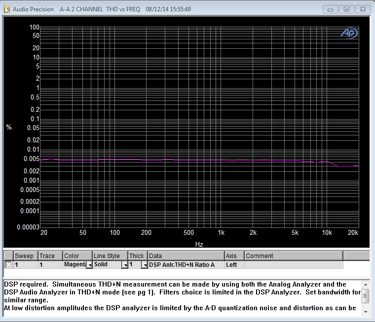
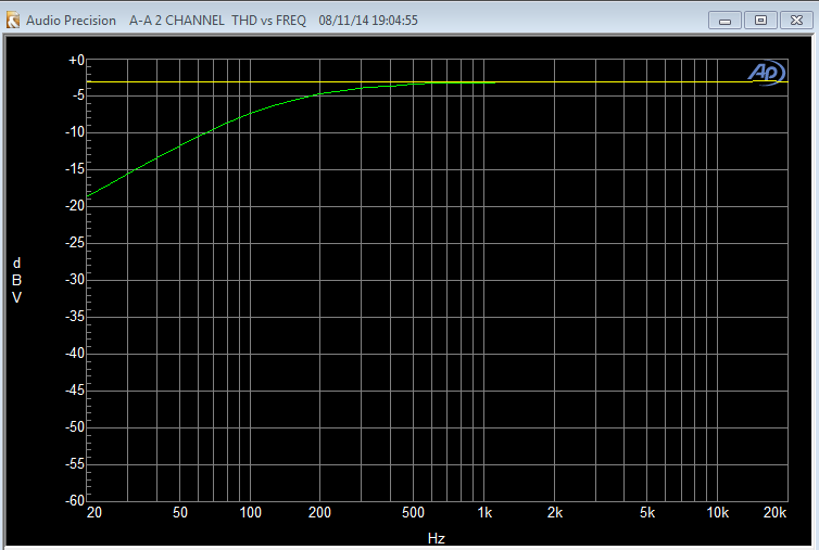
We have obtained the evaluation result that THD+N is degraded below approximately 300Hz when inputting with 0dBFS for the headphone output(DAC playback).
Could you please share us if you have the evaluation results of "THD+N vs Frequency" since we would like to compare them?

Best Regards,
Kato

  • Hello Kato-san,

    I'll check to see if we have any THD+N vs frequency data available.

    Usually when I see this low frequency distortion it's caused by a high pass filter (usually a DC blocking cap) that isn't the optimal value, possibly causing the attenuation in the low end of the spectrum. You could start by looking at that.

    Please let me know if you need anything else,

    Nate

  • Hi Nate-san,

    Thank you for your quick response.
    I have evaluated THD+N via the external I2S, used 100uF as the value of the dc-blocking capacitors for the headphone output pins which are mounted to the TLV320DAC3101 evm.
    I am looking forward to hearing from you.

    Best Regards,
    Kato

  • Hello Kato-san,

    I ran some tests today and also saw higher THD+N on the EVM. I was testing the AIC3111 which is the superset device for the DAC3101. My sweep came out a little weird but I did get a gain vs. frequency response and it showed too high of a cut off frequency for the headphone output

    The green is with 47uF DC blocking caps found on the EVM. The yellow is with them shorted.

    What happens if you short your DC blocking caps? does that solve the problem? this might suggest that bigger caps are required, though 100uF is already bigger.

    Please let me know if shorting the caps helps, if not it is likely caused by something else,

    Nate

  • Hi Nate-san,

    Thank you for your cooperation.
    As you said, I will be shorted both terminals of the dc blocking capacitors, evaluate THD+N.
    By the way, could you please share your measurement result of "THD+N vs Frequency" to us for the dc non-blocking capacitors and 47uF?

    Best Regards,
    Kato

  • Kato-san,

    I would be more than happy to share the results. I'll have to redo the measurements to make sure everything is accurate. I should be able to get this done by tomorrow.

    Please let me know how shorting the capacitor works out,

    thank you for the patience,

    Nate

  • Hello Kato-san,

    I redid the tests from last night and got much better results by using the digital analyzer instead of the analog one on the AP. I ended up with a flat requency and amplitude response with no load but with load I can recreate your issue. When bypassing the DC blocking caps the response became flat again.


    The purple line is without load, the blue line is with 32 ohm purely resistive load and the green is with load but with the DC caps bypassed. This suggests that this distortion is caused by the high pass filter created by the capcitor and load.

    Please let me know if you need anything else,

    Nate

  • Hi Nate-san,

    I greatly appreciate for the answer, understood that the cause of the THD+N degradation depends on the high pass filter.
    Is THD+N able to be improved for the low frequency by changing the type of capacitors(e.g. the aluminum electrolytic capacitor)?

    Best Regards,
    Kato

  • Hello Kato-san,

    I wouldn't expect a different type of capacitor to affect this THD+N. Usually the only time the type of capacitor matters when talking about linearity, but if the DC block cap is of good quality (i.e. linear with voltage and temperature) and rated for at least twice what the expected voltage it will experience (this ensures it operates in the linear region) then the type of capcitor wouldn't make much of a difference here.

    The THD+N at the low frequencies seems to be caused by the high pass filter, so the only parameters that affect this are the capacitor's value and what the load is.

    Hope this helps, Please let me know if you have any other questions,

    Nate

  • Hi Nate-san,

    Thank you for your advice.
    I understood that the capacitors which are used on the high pass filter must be increased, the low cut-off frequency must be decreased  to improve the THD+N degradation.
    Is my understanding correct?

    Best Regards,
    Kato

  • Kato-san,

    This is correct, assuming you have no control over the load, which is typically the case for headphones. Increasing the capacitance will bring the cut-off frequency lower so you will get better bass response and better thd+N at lower frequencies. Increasing the impedance of the load (high resistance load) will have the same effect, but this is probably out of your control and depends on the user.

    Best regards,

    Nate

  • Hi Nate-san,

    Thank you for explaining so politely.
    I understood, will contact you if I have any questions.

    Best Regards,
    Kato

  • Hi Nate-san,

    For the cause of the THD+N degradation, I believe that the fundamental wave is decreased in the low frequency band by the high pass filter, then the noise is constant, therefore the signal to noise ratio is degraded.
    Is my understanding correct?

    Best Regards,
    Kato

  • Hello Kato-san,

    Yes, this is correct. Since THD+N is measured relative to the fundamental tone, if this is attenuated you will see an increase in THD+N.

    Best regards,

    Nate


  • Hi Nate-san,

    Thank you for confirming.
    I understood, will contact you if I have any questions.

    Best Regards,
    Kato