This thread has been locked.

If you have a related question, please click the "Ask a related question" button in the top right corner. The newly created question will be automatically linked to this question.

PBTL with TPA3121D2

Other Parts Discussed in Thread: TPA3121D2, TPA3106D1, TPA3110D2

Hello there,

i need around 50WRMS out of a 24VDC Source (Battery)  into 4Ohm.

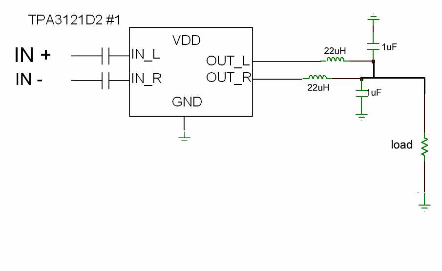
My first try was with two TPA3106D1 wich i built up similar and connected the outputs after the output filter (PBTL). With this setup i reached my goal. Since i have delivery problems with the TPA3106D1 i switched to the TPA3121D2, but here is where the trouble starts:

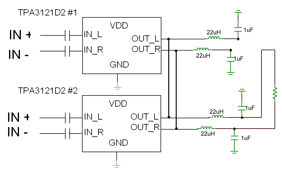
I have two similar built up Amplifiers with the TPA3121D2 and if i just use one of them they work perfectly. As soon i connect the power supply and the signal of the second amplifier without connecting the outputs i get a worse output noise on the working amplifier and the current raises, even without input signal.

Now my question can i use two TPA3121D2 in PBTL and if so what is to consider ? (Inputs and Outputs inverted? / additional filters?)

  • Hi Martin,

    One of TI's Audio applications engineers, Andres, is looking into this issue.

    Regards,
    Aaron

  • Hi Martin,

    I'd be happy to help you. First let me ask you some questions,

    1) How much output noise are you measuring before and after connecting the second amplifier? Same for supply current.

    2) Does the problem arise when you short the inputs for both devices or when you connect the power supply to both devices?

    3) Are you using a TI EVM or your own design? If it is your own design, sending me a schematic and layout would help debugging your problem.

    Regards,

    Andres Blanco

  • thank you for your time,

    i will built up the amplifiers again and give you better info and the schematic tomorrow

    whats youre email Andres ?

  • Hi Martin,


    I looked at the TPA3121 datasheet and it looks like it doesn’t support multiple class D amplifiers like the TPA3106 does, since the user cannot sync the clocks on the different amplifiers. Also, even if PBTL worked, I don’t think you would be able to reach 50WRMS with a 15V supply and 8 ohm load since the device is spec'd at 30W for a single device and PBTL will not double the output power. I can help you pick the right device, but I will need more information on you application:


    1) What is the min power spec

    2) What is the maximum power supply voltage

    3) What is minimum load impedance


    Basically I think you need a higher power supply and lower impedance load, so how far can you go?


    Regards,

    Andres Blanco


  • Hello Andres,

    i know about the power, this is just my experimantal setup, i think the amps have a better chance to survive with this supply and load.

    The load will vary between different 4 and 8 Ohm. But i only expect the full output power at 4 Ohm with 24VDC.

    My goal is around 50 WRMS wich makes sense in my application. As said with 2 x TPA3106 in PBTL , 24VDC and a 4 Ohm load (resistor not speaker) i have good results.

    Of course it has not to be the tpa 3121d2, it was a price/availability oriented decision. If they dont support the PBTL function then i switch back to the TPA3106 or another from you suggested D-amp.

    thank you for youre time M.Haag

  • Hi Martin,

    I tested two TPA3121 devices in BTL today and I was able to achieve 60W at 10% THD into 4 ohms, 22V PS. I also measured higher output noise (250uV) compared to normal BTL (125uV). I think this is due to the parallel outputs adding current noise. I'll go back to the lab tomorrow and see if I can improve the noise performance. Please see attached file to see a high level schematic of what I tested. The way I designed the circuit makes clock synchronization a non-issue. Let me know if there are any differences between your circuit and my schematic so we can see what is causing  your problems.

    Regards,

    Andres Blanco

    TPA3121_PBTL.pdf
  • Nice,

    this really looks different then mine schematic. I will try youre setup today and get back to you soon.

    Regards,


    Martin Haag

  • Hi Martin,

    Let me know the results. Just out of curiosity (and for future reference) what were you trying earlier?

    Regards,

    Andres Blanco

  • Never mind,

    I just saw that you posted your schematic.

    Andres

  • Hi Martin,

    I noticed on your schematic that you are shorting the outputs before the filters. Is this schematic correct? On your original post you said you were shorting the outputs AFTER the filter, which is the correct way. Which one were you trying?

    Regards,

    Andres Blanco

  • Hi Andres,

    i made a mistake in my drawing. I have shorten the outputs after the filter.

    I have connected the amplifiers now after youre schematic but the problem seems the same. There is some noise around every 500ms at the output speaker. Sometimes i get the correct output signal for a few seconds.

  • Hi Martin,

    Could you send me a complete schematic of your design. Last time you sent me a layout and I cant really do much with this. Also, do you have any waveforms that you can send me?

    Have you tried using my design without using BTL. That is, connect the load to one of the amplifiers and the other side of the load to ground. Effectively, this is parallel single ended. Let me know if this works, this could narrow done the problem.

    Regards,

    Andres

  • Hi Andres,

    i will send you my schematic and a waveform.

    parallel single ended:

    Before i built it up, is this correct or have i understood something wrong?

  • Hi Martin,

    Do not put differential inputs, since you are shorting the channels at the outputs. Instead feed the same signal to both inputs. I have attached a corrected version.

    Can you also give me a better description of the noise? Is it periodic or is it just really bad white noise? Is it audible?

    Regards,

    Andres Blanco

  • Hello Andres,

    Where do i connect IN -        

    I already tried this setup with IN- connected to GND, then i get a DC output without any signal in it.

    I sent you a waveform from the noise of another setup today.

    Regards

    M.Haag

  • Hi Martin,

    You'll need a single ended signal generator to run that test. The signal generator will provide a IN+ and GND. If you do not have this generator, dont worry about it for now. Your waveform is a lot different than mine, which means there is a big difference in the circuits and we need to figure out what it is. I'll take a closer look at your schematic and see if there are any differences.

    Regards,

    Andres Blanco

  • Hi Martin,

    A couple of questions:

    1. In the last email you sent me, you said "All four Signal inputs are shorted" but there are some signals in the output waveforms. Is this correct? Are you saying these signals generated by the amplifier?

    2. What is the voltage scale on the waveforms?

    Regards,

    Andres Blanco

  • Hello Andres,

    yes these waveforms i sent you are generated from the amps. If you need the exact Voltage scale i have to calibrate my Scope. But the Peak is nerby VDD.

    I have a sine / square / triangle -wavegenerator

    My guess is that the amps swing each other higher until it shuts down because of an overload, after around 500ms the amp reactivates and all starts again. As said, sometimes i even get some seconds the correct output. But most of the time the amps are just switching on and off.


    Regards,

    M.Haag

  • Martin,

    Do you have any equipment other than the osciloscope, to measure the output. I was having an issue yesterday with an oscilloscope probe that was causing an oscillation at the outputs similar to what you are seeing. I used another probe and the oscillations went away. Also I connected a speaker to the outputs when they had the oscillations and I could hear a periodic click. When I disconnected the probe, the click went away and I could hear music.

    Careful connecting the speaker to the outputs, since I dont know how much power your waveform is carrying and it might be too loud for a low power speaker.

    Regards,

    Andres Blanco

  • Hi Andres,

    i have checked the influence of my osciloscope and as far i can say there is no difference. If i connect a speaker  the noise stays the same weather the osciloscope is connected or not.

    I have also tried with a different power supply for each amp without solving the problem.

    What might be interesting is, if i force one amp wich usually works correct, to shut down (24VDC , 4 Ohm load , very high input signal) i get a very similar output with this periodic noise.

    Regards,

    Martin Haag


  • I have news,

    after some try and error modifications i have found out that the two amps work better if i connect the ground on another spot. But the performance is very weak above around 10 Watts the musik sounds unclear. I will order some other D-Amps today and try my luck with them. I wont do anything with the TPA 3121d2 anymore unless you can give me other ideas.


    thank you for the support so far,


    Martin Haag

  • Hi Martin,

    I just sent you an email asking for more information about the strange behavior, but I guess the noise is no longer present. I am assuming the 10W is with a 24V and 4 ohm load, which is very low for this device. Have you measured the THD of a single tone signal at 10W? Also, what D-Amps are you considering? Are they TI parts? If they are, I could help you with that too, just ask!

    Regards,

    Andres Blanco

  • Hello Andres,

    i think i will go with the TPA3110d2 with two amps in PBTL  again. In addition i will built up the TPA3106 again.

    Wich type would you suggest for this application ?


    Regards,

    Martin Haag

  • Hello Martin,

    When you say 10Wrms, is it music or a sine wave? 10Wrms for music seems reasonable for a 50W amplifier. Did you do this same test with the TPA3106?

    Regards,

    Andres Blanco

  • Hi Andres,

    i cant measure THD and i cant measure the power of a music signal.

    I measure the RMS Voltage i get at the output without any distortion on my osciloscope. If i do so i use a  sinewave (usually 50 and 1000Hz) and a resistor as load. With that setup i compare different amps.

    With two TPA3121 i just dont get a stable circuit. If i raise the Supply Voltage gentle sometimes it works, if i switch from 0 to 24VDV i have the 500ms intervall clicking noise. If everything works i just have to touch GND with my fingers and its the 500ms intervall clicking noise again.

    I have invested now a lot of time and i think i reach my goal faster if i try another circuit.

    i will open a new discussion if i have problems with the other amps..


    Regards,

    Martin Haag