This thread has been locked.

If you have a related question, please click the "Ask a related question" button in the top right corner. The newly created question will be automatically linked to this question.

LM49352 Class D output issue

Genius 3475 points

HI

My customer is using the LM49352 for his project. We managed to setup the codec to accept input via port 1 (i2s), in & out via port 2(i2s) and to drive am 8 ohm speaker via LS+/- differential. There is a mic input as well.

all other peripherals are not needed and switch off accordingly


The master clock is from an external MCU. Port 1 is accepting data input from the same MCU. Port 2 is communicating both ways to an external module (master, i2s clock from this module ).

When power up, the MCU would write in thru I2C all register values into the Codec. We are sure the I2c is working fine as there is an exception capture on I2C failure and also a read back verification of some registers.

After power up , there is a pair of identical 300KHz square wave  at LS+ and L- (measured against ground). We believe the Class D is functioning ok as well. As specified by the data sheet on page 39

When we send in the data via I2S port 1, there is no output from the speaker. The waveform taken is unchanged from above paragraph, we assume there is no output from the DAC upstream (including the port 1 mux or the i2s “de-serealiser etc”.

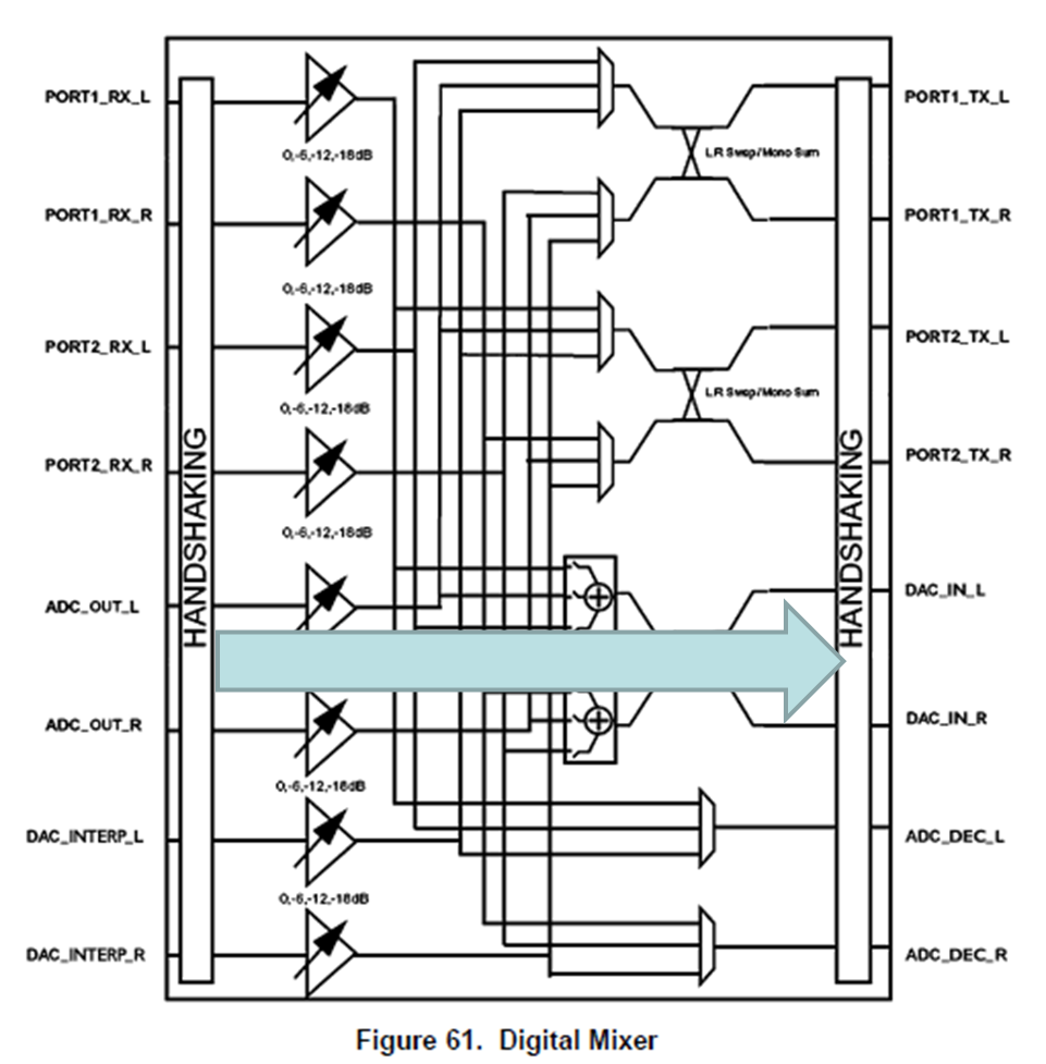
We tried to by pass the i2s portion by trying to use MIC in, ADC, mux back to DAC (thru the digital mixer), to LS. It did not work as well. No sound(or correct switching waveform) was observed at LS output.

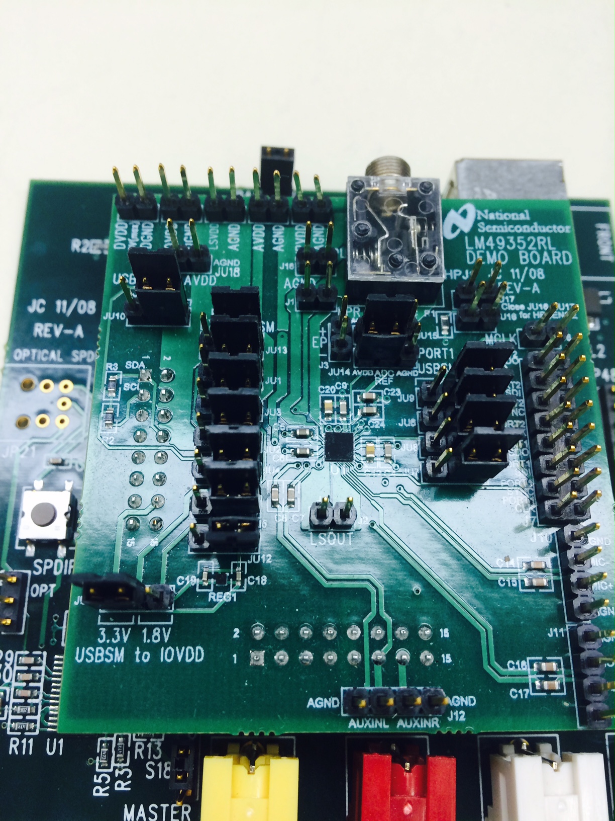
I have attached the initial register setting for your information

Kindly advise if there are other ways to further isolate whether it is a data problem or analog error

Ivan 

6505.Initail reg setting.xlsx

  • Ivan,

    I will take a look through the registers sheet you sent.  I have a EVM locally that I will dig up and try testing this one and get back to you.

    -Matt

  • Hi Mathew
     
    Would you be able to share the schematics of this EVB if possible. It can no longer be found on line.
     
    I was actually working with some Avnet colleague and local TI team. Would you mind if I add them in the CC?
     
    With the EVB and the GUI you should be able to effect any changes very quickly and test out. The most important feature is the export of register setting as a .352 file (text) that we can put in the MCU to quickly do a local test.
     
    Can you help us do a quick export of registers for below senario

    ·         Port 1 to Port 2 (SPI) loop back via the Multiplexer, OBJ: to check if the I2S setup is correct


    ·         Port 1 to Port 2 (SPI) loop back via DAC and ADC, OBJ: if I2S is ok, did we set up the ADC and DAC correctly


    ·         Direct MIC drive to LS +/- , OBJ : Is the analog path working. This test is independent of i2S


    Ivan Ng
    FAE
    Asean
    ivan.ng@avnet.com
    151 Lorong Chuan
    #06-03 New Tech park
    Singapore 556741
    Office:
    +65 65804706
    Cell:
    +65 96995985
     
     
    From: Matthew Kucic [mailto:bounce-1879535@mail.e2e.ti.com]
    Sent: Friday, October 03, 2014 3:33 AM
    To: AudioConvertersForum@mail.e2e.ti.com
    Subject: RE: [Audio Converters Forum] LM49352 Class D output issue
     

    Ivan,

    I will take a look through the registers sheet you sent.  I have a EVM locally that I will dig up and try testing this one and get back to you.

    -Matt

  • OK I think for the debug you need to start with the defaults and enable each block one at I time.  I am using a Audio Precision on Port1.  I power on, Set the correct rates for Audio Port1(0x50-0x56) enable port1 to the DAC(0x44) and route the dac to the LS or HP(0x10 or 0x11).  It works.  I am not using the PLL.  I see you have the PLL enabled.  Why is that?  If there is a reason please supply the clock rates you are using to I can reproduce.  I tested with MCLK=12.288, BCLK=3.072, L/RCLK=96k and FS=48khz.

    Something I did notice is that when I changed the PMC clock from MCLK to Internal OSC like you have the audio stream stopped over the PORT.  can you try setting this back to the default MCLK and /by 40.5?  If I just routed the AUX to HP/LS I could use that clock.  Also if I ran the DAC path clock from Port1 vs MCLK it worked.  So maybe this is the source out your no audio.  BTW you cannot route the mic to HP/LS directly in the analog mixer.

    I also ran mic->ADC->DAC->LS and it worked.  But again I am not using the internal PLL just MCLK.

    I have attached a couple of the .352 files you were looking for below.  If I get the clks I can setup the AP with the same and check using your PLL settings.

    Also on the xls sheet the DAC 0x30h says Set for the Mute_L.  I would assume this is 0 when trying to get audio out.

    Finally I do not have the schematics for the EVM.  The best I could find is the 49350 which is pretty close.

    -Matt

    http://e2e.ti.com/cfs-file.ashx/__key/communityserver-discussions-components-files/64/5023.I2S_5F00_PORT1_5F00_48khz_5F00_256FS_5F00_2ch_5F00_32bit_5F00_TO_5F00_LS_5F00_output.352

    http://e2e.ti.com/cfs-file.ashx/__key/communityserver-discussions-components-files/64/6837.ADC_5F00_DAC_5F00_LOOP.352

    1440.LM49350demoboardv3.pdf

    3617.SubsystemMotherboardv2_sch.pdf

  • HI Matt

    I have one of the board.

    Can i check with you on your jumper settings for both the USB Subsystem Motherboard and the LM49352RL Demo board?

    What is the OS you are using to run the LM49352 I2C interface software V1.0 ?

    I am getting an error of 

    " an error has occured in the initialization of the LM49352 I2C interface"

    Ivan

  • hi Matt,

    Customer were to use port #1 for mono 16 bits PCM (uplink and downlink), and port #2 for stereo 24 bits I2S (downlink).

    Port #1 is working fine, but port #2 still in debugging stage.

    Can you pls advice register setting on 0x60 to 0x65 in order to support 24 bits stereo I2S? Thank you.

    regards, Ken

  • The software will only run on windows xp.  Attached is a picture for the jumper settings to allow the device to run completely over USB.  If the ADC ref is not setup as below it will not work over USB I found.

  • Ken,

    It depends all on the I2S configuration like Master / Slave for clocks.  You should be able to figure this out with the GUI now that you have a evm.  If you have a specific question about these register settings let me know and I can answer them if you have not already figured this out.

    -Matt