This thread has been locked.

If you have a related question, please click the "Ask a related question" button in the top right corner. The newly created question will be automatically linked to this question.

Distortion at High Temperature, TLV320AIC1110 in 8-bit companded mode, Analogue to Digital

Other Parts Discussed in Thread: TLV320AIC1110

I would be keen to hear from anyone who is using the TLV320AIC1110 at high temperature (~ 70C), or who might be able to suggest possible causes of the following...

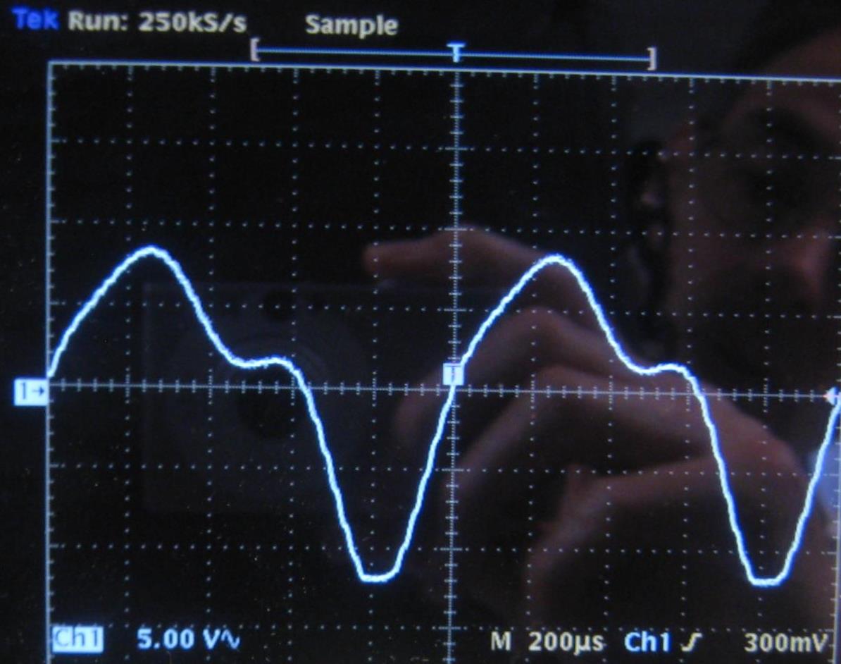
The device / circuit works as expected at room temperature.  It's in the 8-bit companded format.   Digital to analogue side works fine at all temperatures tested.   At high temperature the analogue to digital path shows little distortion as the temperature rises until it reaches some threshold (varies part to part, mostly around 70C but some as low as 50C).  Above that, distortion rises gradually with increasing temperature and becoming really bad (eventually to 100% as calculated by using FFT).   The distortion is visible just looking at the data with a scope (two codecs in parallel, heat one, see MSB go wrong on hot one).  Using another codec to convert back to analogue allows me to see that as temperature rises, the distortion worsens (I'll add images).  The problem is not sensitive to amplitude or to the exact shape of the clocks.  The problem is not new, however it seems to have got much worse this year. 

  • Here are scope plots of the distorted digital PCM converted back to analogue. 

    1st <1% THD (room temperature), 

                                   2nd shows more distortion as temperature rises, 

                                                                    3rd image shows 37% THD when hot. 


    All inputs except temperature stayed the same.  For convenience in the lab the codec chip is being heated directly by a power resistor stuck to the plastic body, however I get identical results when the device is in the equipment in a thermal chamber, heated by the hot airflow, with the chip package temperature monitored.

    Experiments with the Rext 100K and with small capacitors on various pins made no difference.

    This product is required to keep working with intelligible speech even when hot (never above 70C).  Our production test pass/fail is 10% THD for this high temperature test so it's pretty relaxed - the failure is a gross problem.  Today I have a pile of at least 50 failing boards but they all seem to do it at some temperature, including new samples of the device.

    I'll have to get a black glove for taking photos!

  • Hi Ian,

    Could you provide more information about your circuit, the setup of the part and how are you powering the part?

    Justin

  • Thanks for your interest in this.  I've attached an extract from our circuit.  The 3v3 supplies look clean, very close to 3V3 nominal and well filtered.   We are experimenting with varying the voltages.  While continously powered, the phenomenon comes and goes as temperature rises / falls (and the analogue input looks OK at chip pins).     Strangely  as we conduct different experiments on different days the temperature at which it happens seems to vary widely.

    We can capture actual I2C data with a logic analyser if required but the software is intended to configure to:

    • POW_REG = 0x9B (Sidetone Mute, TX en, MIC1, Rx en, EAR AMP1, Ref P Up)
    • MODE_REG = 0x12 (U law companding, slope filter enabled)
    • HI_DTMF_REG = 0 (DTMF to no freq)
    • LO_DTMP_REG = 0
    • AUX_REG = 0 (default)
    PCM Codec schematic extract, edited.pdf
  • Hi Ian,

    One place to always investigate when running into Audio output problems is the clocks. Could you share more information about the clocks going to the part, and if they may be close to the data sheet limits? By your settings MCLK should be 2.048MHz, is this correct?

    Justin

  • Yes, it is within approx. +/- 100ppm of 2.048MHz and the two clock inputs are tied together.    Although the circuit extract attached above shows a slightly complicated arrangement whereby our software can control a VCXO over the +/-100ppm range round nominal (required to maintain a buffer depth in another remote system down the digital chain), the problem happens just the same when I disabled that.  I checked but found no small glitches during rise/fall of the clocks. Adding small capacitors from MCLK to Gnd did not seem to change the temperature where it happened (tried 33pF) which makes me think it's unlikely there are small glitches we are sensitive to.  It also makes me think that we are not very sensitive to rise/fall time (though it would be great if that turned out to be the problem - we might be able to adjust that in the programmable logic device.  This is an area I intend to explore further.  The board is many layer with good ground and power planes.  The clocks look clean (hot or cold) with a normal 'scope .... I've not tried a very high performance scope / probe.... on the list of possible "long shot" experiments.  The programmable logic device that distributes the clock and sync is Flash based, not SRAM so the clocks should be OK soon after power-on.   The sync is a single clk long.  The reset is activated well after power-on  and note that the problem recovers when temperature falls.  I am curious to know more about the PLL function - is there an analogue VCO in the chip or is it a DCO (all digital, eg digitally controlled ring oscillator)?

  • Hi Ian,

    I am not sure what is driving the PLL but I will try to find out. Are you able to test an EVM in a similar situation to see if it will fail the same way?

    Justin
  • Hi Justin, Work in progress re EVM.  I've started a separate thread re problems were having with the EVM software installation:

    http://e2e.ti.com/support/data_converters/audio_converters/f/64/t/389394

    I'm now feeling stuck  and needing help with the EVM installation.  

    On my own mini-EVM (I did a PCB with just enough to use the chips in default mode), I've confirmed that one new (sample) chip works over a wide temperature and frequency range.   The frequency range only changes slightly with temperature.   I'll next do the same again but varying supply voltage, just to check range at temperature.      On a failing production board, we previously saw good analogue into the chip at the same time as bad PCM out - now gradually trying to get back to that - it does not seem to be happening with wires attached (or maybe something else is changing).

    Ian

  • We did eventually crack this problem.   The cause was current leakage through the reverse biased mic input protection diodes (which increased with temperature).  The designer had not appreciated the significance of the datasheet limit of +/-300nA max input bias current - it was probably assumed that this was a characteristic of the chip rather than a requirement of the circuit.   What I found is that although the differential input impedance may be per datasheet, the common mode input looks like an insulator.   An experiment indicated that the common mode input resistance was higher than our DVM!    How the input bias works is a mystery within the chip - it does work very well provided we don't cause more than 300nA to flow in or out.   

    One reason the root cause eluded us for so long was that the input signal looked undistorted - the problem being caused was inside the codec chip.

    Simply changing the diodes to a low leakage type fixed the problem.

    By the way, we never did get the EVM software sorted out but in the end that did not matter.

    In retrospect, the problem could have been avoided if the datasheet had enough information about the chip input to more clearly warn against allowing input current over 300nA.   I do have a concern that humidity / dirt could cause some leakage, especially in a condensing environment.

    Apart from this problem, our extensive experiments showed that this is a fantastic chip; really tolerant to just about everything else.  It's performance is remarkably constant across temperature/voltage/clock speed etc.

    Many thanks for your interest and support.

  • HI Ian,

    I am glad you were able to find a solution, and appreciate that you posted your finding on E2E for others to be able to utilize. We will note the changes for the data sheet to make this more clear.

    Justin