This thread has been locked.

If you have a related question, please click the "Ask a related question" button in the top right corner. The newly created question will be automatically linked to this question.

EMI problems when using a TPA3110D2

Other Parts Discussed in Thread: TPA3110D2

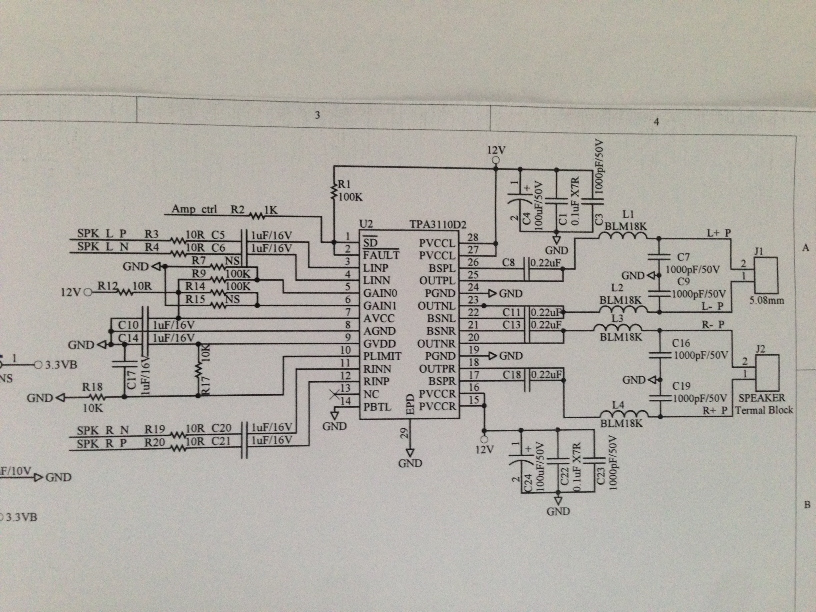
Can anybody from TI help with a problem that we are having with Radiated and conducted emissions on an amplifier that we have had designed for us. We are using a TPA3110D2 Chip  with a 12v supply.  We believe that we are achieving an 8 watt output into 2x  8 ohm speakers. One of the speakers has a cable length of 120 mm and the second speaker has a cable length of up to 10 meters.

  • Hi Mark,

    have you implemented a simple output filter just with ferrite beads or the proper one with inductors? I guess 10m speaker cable is way to long for using simple ferrites as output filter :) Is the speaker cable twisted as suggested in TI d/s? Have you placed additional snubbers?

    Cheers,
    Tomasz

  • Hi, Mark,

    As Tomas mentioned, try out the output snubbers and inductor filters. This should solve your EMI issue.

    reg,

    Paul.

  • Hi Tomasz,

    The design is without snubbers and is built as per page 20 of the Product folder ( july 2012) with FB=BLK18K . The speaker cable used is not twisted.

    Regards,

    Mark.

  • Hi Mark,

    If you like you can share with us some more details about your design so I could take a look.
    - what exactly type of ferrite bead it is
    - what types of capacitors you used - is also quite important for the EMI performance
    - how does your PCB layout look like? Could you post a picture to illustrate the output section of your amp?

    Tomasz

  • From the other side, have you tried to perform the EMI tests with short, like TI defined 120cm, twisted speakers cable? it should make a difference. Is it FC or CE certification you are doing or something else? Could you tell me also what exactly makes your problems - what level over limit @ what frequency?

    Tomasz

  • Can I send you the files directly of the EMI problem scans ? Or do I need to send them through the website ?
     
     
    Mark
     
    From: Tomasz J. Chumiecki [mailto:bounce-1167644@mail.e2e.ti.com]
    Sent: Saturday, 6 December 2014 12:01 AM
    To: AudioAmpsForum@mail.e2e.ti.com
    Subject: RE: [Audio Amplifiers Forum] EMI problems when using a TPA3110D2
     

    From the other side, have you tried to perform the EMI tests with short, like TI defined 120cm, twisted speakers cable? it should make a difference. Is it FC or CE certification you are doing or something else? Could you tell me also what exactly makes your problems - what level over limit @ what frequency?

    Tomasz

  • Tomasz,

    The test is for EMI with relation to CSPR13. I have tried using a shorter twisted cable but this does not fix the problem

    Mark

  • Mark,

    you can send me all details at tomasz (at) chumiecki . com , its my private email. Weekend is coming so I can take a look on it - maybe we can find some solution. At the first look it doesn't look good :) Have you considered using a standard output filter section with real inductor, snubber and capacitance about 1µF? Placing a standard output filter + snubber + common mode choke would probably solve the problem - the question is how cost and space sensitive your project is.

    I will take a detailed look and replay soon.

    Tomasz

  • From the other side would be nice, if someone from TI take a look on the measurements you posted and compare it to the performance of the original TPA3110D2 TI evaluation module. Would it be possible to see the EMI performance, the measurement done by TI on the original TI evaluation module? I guess only TI is able to judge what is possible to reach with simple ferrite output filter stage and where is needed to use the inductors.

    Can someone from TI share the EMI performance of TPA3110D2 TI evaluation module here?

  • Hi, Mark,.

    For conducted EMI, the power supply's ability to filter play a significant role. Avoid routing the speaker wires close to the AC line since the PWM output can be coupled to the AC line directly and bypassed the power supply filters. Try LC filters such as (15uH to 22uH inductor) + 0.68uF cap.

    reg,

    Paul.

  • Paul,

    the first question is, should the TPA3110D2 TI reference design with the off-the-shelf consumer power supply and the simple output filter like in the d/s: FB + 1nF MLCC, pass the CISPR13 in range from 150kHz - 5MHz? I do not think so... but I'm not an EMC expert therefore I can be wrong...

    I took a part in this discussion because the EMI issues are also very important my projects to and I would like to extend my own knowledge in this area too.

    I'm sure implementing LC output filter even with 10µH with 0.68µF-1µF high quality capacitor - MLCC or metal foil, adding snubbers and common mode choke on output, placing good decoupling capacitors for power stage + right layout will definitely solve the issue, but... it increases significantly cost of the design and make it much bigger :( This is why I'm asking if the standard TPA3110D2 TI reference design should pass the test.

  • Mark,

    what is your goal - just to fix the EMI performance even increasing cost and size of the design? Is the redesigning of the output filter a solution for you? can you accept adding some additional components just to pass the CISPR?

    or your goal is to get the TI design like it is passing CISPR...?

    Taking look on your measurements, specially in the 150kHz-5MHz range I am really skeptical you can reach it with FB based output filter...

    Tomasz

  • Hi, Tomasz,


    In the past we have performed conducted emission measurements with our EVM in a consumer TV with stock FB filter and passed EN55022 Class B.

    However, with AC warts or power bricks supply, it will be quite a challenge to pass with FB filter. Usually an LC filter is required.

    reg,

    Paul.

  • Paul,

    this is what I would suggest - replace the FB output filter with LC one, use snubbers, take a look on decoupling caps and in case of hard radiated emission problems use common mode choke on output.

    Tomasz

  • Hi Tomasz and Paul,

    This is a current drawing of the design

    I appreciate your help with this issue.

    regards

    Mark 

  • Tomasz,

    The goal is to fix the problem ASAP with what ever we can taking into consideration cost and board size. Our subcontractor is not an expert in this field of amplifiers and EMi and is asking us for our input. We are trying to get it right this time with one more sample run as it is becoming very costly to keep on producing samples to continue to fail.

    Best regards,

    Mark.

  • Hi Mark,

    sorry for the delay, I had a bit busy weekend what I didn't planed so ;) Lets summarize what we have now:

    1. what I understood up to now is that TI can not guarantee you can pass your CISPR13 EMI requirement with the simple ferrite bead output filer, and surely with 10m speaker cable... with this 10m long speaker cable I would be very careful with EMC performance...

    2. you could try implementing snubber, decoupling caps and optimize your your layout but... passing the test would be not guaranteed...

    3. your goal is to fix the problem ASAP with what ever you can taking into consideration extra cost and board size. Your subcontractor is not an expert in this field of amplifiers and EMI and is asking for an input.

    So my suggestion is:

    - to definitely replace the ferrite bead based filter with the LC one - I don't think would be a really cost driver. the PCB area will definitely grow...
    - simultaneously take a serious look on the PCB layout design in a way of EMI performance
    - put even some extra EMC relevant components footprints (like for common mode choke for HF) as an assembly option you can use them if needed, if not you can leave them not populated. Such an option you can use even being in the EMC lab, just to pass the test or to find the optimal design.

    Tomasz
  • If you like you can send me the layout/layout part to review. Your schematic looks like Protel?/Altium? schematic - I unfortunately use the CADsoft EAGLE for everything but we can find a solution if needed :)

    I can try to find for you the possible LC output filter configuration if you like. Even doing the amplifier PCB layout design for you would be possible, but I have to schedule such a task in my time :) In this case we have to contact and discuss some more details.

    Tomasz