This thread has been locked.

If you have a related question, please click the "Ask a related question" button in the top right corner. The newly created question will be automatically linked to this question.

SRC4190 CLOCK CONNECTION

Other Parts Discussed in Thread: SRC4190

Dear Justin,

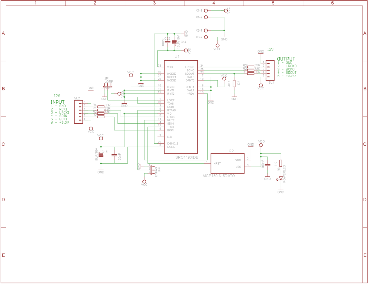
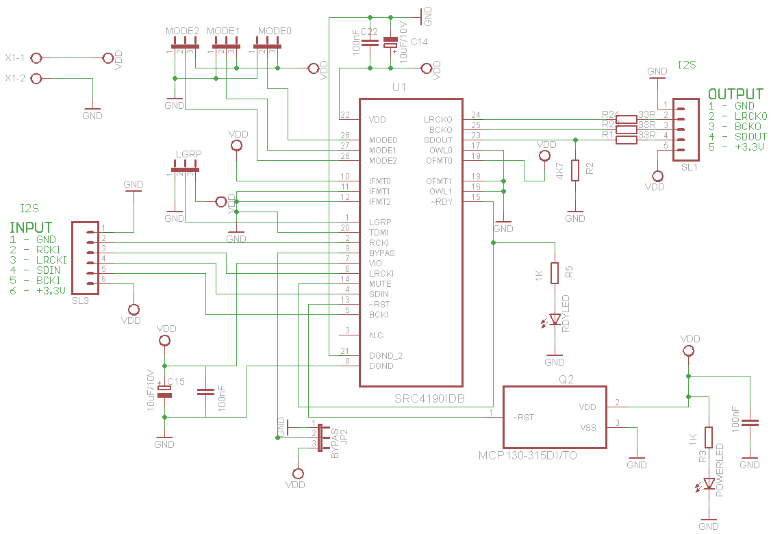
I have made a schematic for SRC4190 which I want to use with the CS8416 to keep the sampling frequency at constant 192KHZ. I have attached here  the schematic. I am using the  clock form the I2S bus of the the CS8416. I am using the Slave Mode for both input and output, With input Data Format being 24 Bits I2S from Digital Audio Receiver CS8416.

I would appreciate if you can check the schematic and give me some feedback.

  • Hi Sidney,

    there are many bugs in your schematics.

    1. Pinout of input I2S connector doesn't respond to description. Connector is from pin 6 to 1 and description is from pin 1 to 6.

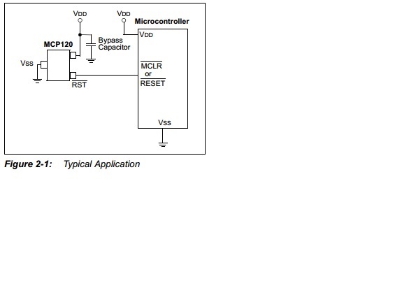
    2. MCP130T have switched pins 2 and 3.

    3. Part of schematics is connected to the VCC and part to the VDD. Why? You can power whole system from one voltage 3.3V.

    4. There are missing junctions in few places.

    5. There are useless junctions in few spaces.

    6. Why your input and output I2S connectors have different pinout?

    Please check every wire of your schematics and compare it with datasheet. This must be done by yourself.

    best regards, Pavel

  • Hello Pavel,

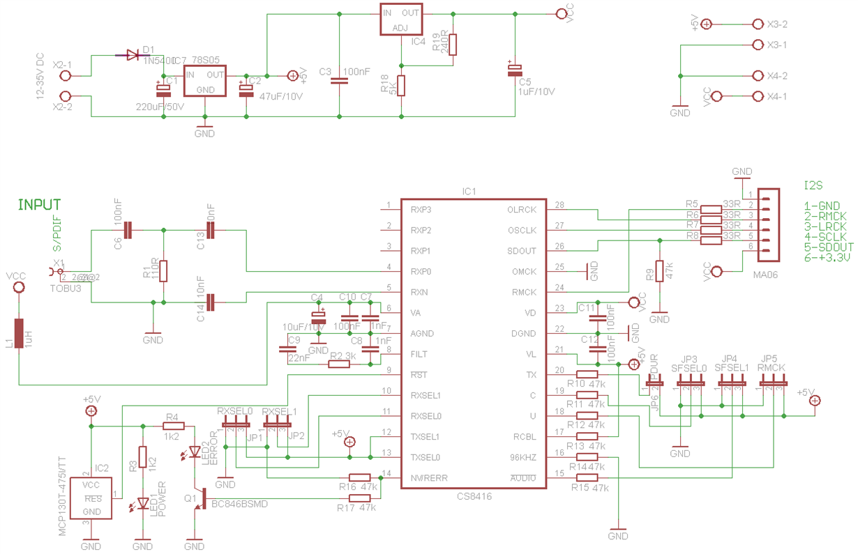
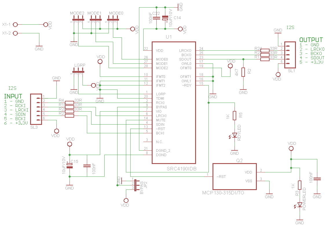
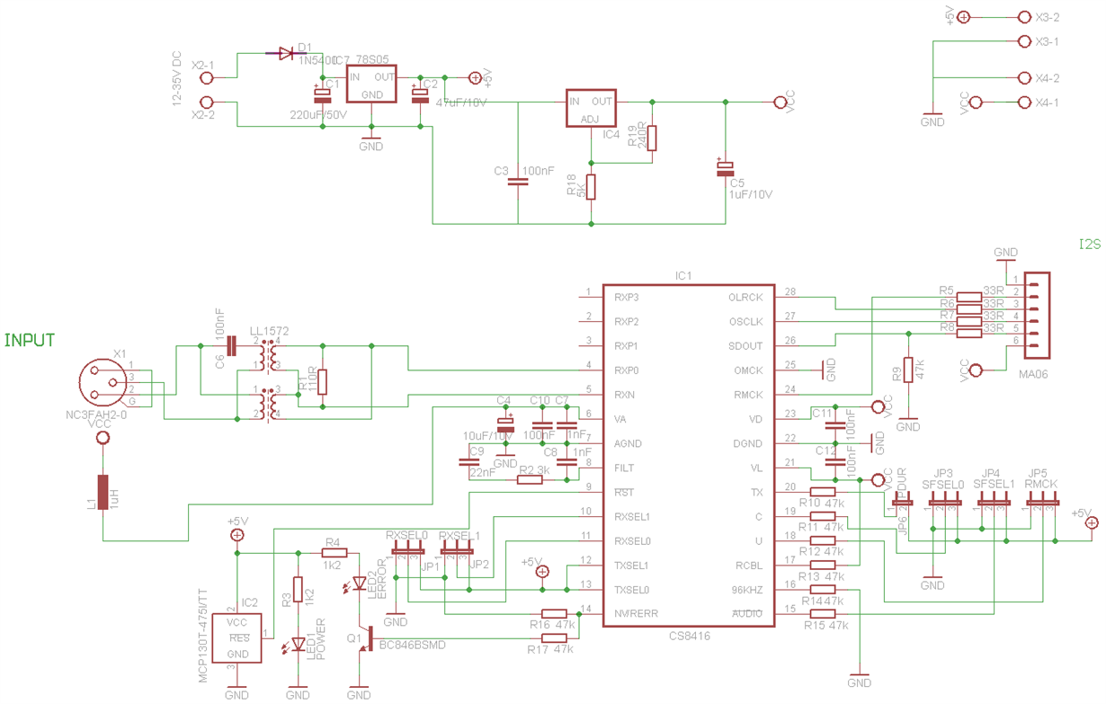
    Thanks for the feedback. I have made some changes in the schematic. I am using your schematic for the CS8164 S/PDIF decoder. I have made some modifications there which I have attached here. my power supply comes from a 12V dc power supply which I have made. The I2S bus at the output of CS8164 is connected to the input of SRC4190. The input of the SRC4190 has 6 pins because the SRC4190 chip is using the the clock RCKI of the CS8164 chip. Meanwhile the out put of SRC4190 has no clock because it will use the clock signal from the DSP.

    I have attached here the modified schematics of CS8164 and SRC4190 together with the connection circuit of MCP130

    I will be grateful to get more feedback from you.

    Kind regards

    Sidney

  • Hello Pavel,
     
    Happy New Year. I have some questions regarding your project "CS8416 S/PDIF Decoder"
     
    I would like to know the setting you used for RMCK and PDUR to achieve 192kHz/24 bits Samples. 
     
    I am Using AES/EBU, can I use the cinch female to PCB TOBU3  at the input? 
    Which type of Ferrite Bead did you use in the CS8154 S/PDIF Decoder project?
     
    Kind regards

  • Hello Sidney,

    For 192kHz you need to have PDUR=0 which mean TX pin unconnected.

    RMCK set system clock 256*fs or 128*fs. It depend what support SRC4190. Look at the datasheet what is suitable for 192kHz.

    If you using AES/EBU, that it can work, but it is not a good idea, because AES/EBU use symmetrical connector and cables with impedance 110R usually XLR.

    Cinch is used for commercial S/PDIF with coaxial cable with typical impedance 75R.

    About your schematics, you can't use +5V on VL pin of CS8416, because SRC4190 use 3.3V logic and not 5V logic.

    If you will have CS8416 and SRC4190 on one board, that you can use one reset circuit MCP130T for both chips.

    I don't remember what ferrite bead I used, but it is not much important.

    Best regards, Pavel.

  • Hello Pavel,

    Thanks for the feedback. I have made some changes in the schematic. I am using your schematic for the CS8164 S/PDIF decoder. I have changed the SPDIF input to AES/EBU input. I have also removed the ground on the Transformer and pin RXN, I hope it will have no effect on the new design.

    I have attached the design here. I am looking forward to get some feedback from you at your convenience

    Kind regards

  • Hello Pavel,

    In the SRC4190 circuit, I also made some modification on this schematic. I have removed the 33ohms resistors at the input pins of RCKI, LRCKI, BCKI, SDIN since they are already present at the output of the CS8164, Can this cause any problem?

    Kind regards