This thread has been locked.

If you have a related question, please click the "Ask a related question" button in the top right corner. The newly created question will be automatically linked to this question.

PCM1865's register configure problem.

Other Parts Discussed in Thread: PCM1865

HI,Tier.Now we need to use PCM1865 to transfer 4 channel audio to TI's dm8168. There are some questions about register configure.

1.Do we need to configure something about DSP1 and DSP2? It is a must or optional part?

2.In Page0,register 11. P75 of datasheet(slas831B-MARCH-2014-REVISED-MARCH-2014).

  The bits RX_WLEN and TX_WLEN means what? The PCM1865 is just a ADC, so the Tx is reasonable. Where the RX_WLEN comes from?

BR!

  • HI,I want to use PurePath Console to debug the PCM1865 EVM.
    But when I do the register dump,it says that "memory dumpfailed".And I can NOT read the register by directyly I2C read write.
  • Hi SuitJune,

    The DSPs have ROM code that runs, what you can modify is the mixer coefficients that control the mixing of the signals ad the coefficients for the secondary ADC for energysense. It is possible with PCM1865 to receive an I2S signal and mix it with the other inputs. This can be done by setting one of the GPIO as DIN. Therefore it is possible to specify the word length that will be input in this pin.

    For the second post, when these errors occurred what did the GUI say in the bottom left? It should be a green power symbol and say that it is connected.

    Justin
  • Thanks for your reply.And I still have some questions.We use PCM1865 as Master.

    1. Could we leave the dsp coefficients data default?We need to transfer four mono 16K audio to TI's dm8168.

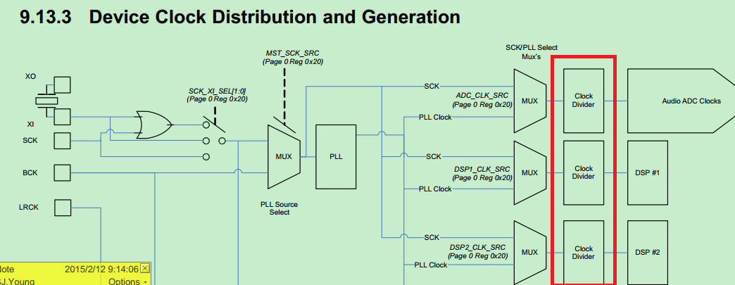
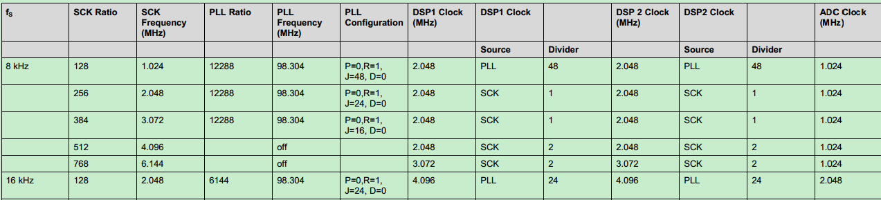
    2.For the below picture,the clock dividers inside the red rectangle,which register corresponds to them?I can NOT find any register corresponding to them in the spec. And for the audio adc clocks, how to decide it? For our case,we need to transfer four channel 16K/16bit audio to TI's soc.then the audio clock= 4*16K*16bit=1.024M?Right? 

    3.what does the SCK ration mean?It often appears in the spec.

    4.For the below picture,What does the clock dividers in the red rectangles mean?

    For register 0x026, from the diagram, it is the "master sck" to bck ration,and the so-called "master sck",in fact, is PLL clock after the clock divider in the green rectangle,or sck.

    For the register 0x027,is the BCK to LRCK ration, for TDM mode,should be 255.But in the register description part, it says that it is "Set the Master SCK Clock Divider value"

    For different parts of the spec,the description for register 0x026 and 0x027 are different.For example, register 0x026.In Table6 PLL configuration table,it is master mode sck to sckout ration.However, in the register part, it says that "Set the master SCK clock divider value.This is ratio of Master SCK to Bit Clock(BCK)".

    For register 0x027.In the register part, it says that "Set the master SCK clock divider value", We do NOT know the exact meaning.However, in the clock tree disgram, it appears that it is the ration of BCK to LRCK.And in the Table6 PLL configuration table,it is "Master Mode SCK to BCK ratio".

    I am totally confused about the register meaning.

    My understanding is right?For the clock divider inside the green rectangle, it corresponds to register 0x025?

    Expecting for any reply.

  • and how to set the sample rate for 4 channel audio capture?
    I find that register 115, show the sampling frequency.But, this register is a read-only register?Or we could write the sample frequency into it?
    Why INFO[2:0]=011,it is 32-48K, is not a specific sample frequency?is just a range?
  • Most questions is caused by that I read a rev B datasheet.

    Rev C datasheet is more understandable. But when I download the Rev C datasheet, in "Revision History" part, do NOT show the ALL modifications in fact, it only shows part of modifications, so I continue to read rev B datasheet.

    But,there is some questions still. Let me read Rev C datasheet firstly.

  •  Hi,TIer. The last problem.

    For the adc clock in the below diagram, how to decide the adc clock?How to get it ?


  • Hi SuitJune,

    This is explained in the data sheet in Figure 29. PLL Clock Source and Clock Distribution.

    Justin
  • I think it can refer to table 9,10,12,13 in RevC datasheet.And the principle is ADC should be fast enough to "sample" the audio.

    No matter what,thanks to your reply.

    BR!