This thread has been locked.

If you have a related question, please click the "Ask a related question" button in the top right corner. The newly created question will be automatically linked to this question.

TPA3118D2 fed from PCM5242 DAC

Other Parts Discussed in Thread: PCM5242, TPA3118D2, PCM5142, PCM5102

Hi,

I implemented the PCM5242 DAC to feed my power stage with TPA3118D2. First I connected the parts directly having just a simple balanced RC filter in between. It does work, but the THD+N increase heavily with the output power. Starting from some good values below 0.05% for low power up to 5% and more at maximum output power. I noticed I definitely need to decouple the PCM5242 DAC from TPA3118D2 input. I placed small DC-blocking caps and everything work perfectly.

Now the question :) Could you shortly explain me, why do I need the AC-coupling caps between TPA3118D2 input and the PCM5242 DAC output? I thought using the PCM5242 DAC with the line driver output, without DC offset, I could connect the both stages directly?

If it doesn't work like that, and if I still definitely need the DC-blocking caps, I could better go for PCM5142. In fact I do not need the 4.2 Vrms output. Even with the lowest gain of the TPA3118D2 I have to attenuate the output signal of the PCM5242 not to overdrive the TPA3118D2.

Cheers,
Tomasz

  • Why man is so blind sometimes? Sure the TPA3118D2 does not accept negative signals... now my question looks like quite stupid when I found the answer taking one more time a detailed look into the data sheet :) Can I feed the TPA3118D2 input without DC blocking caps just simple shifting the input signals adding 1.5V DC offset?
  • Hi, Tomasz,

    The inputs are biased around 3V. I'd not recommend using it without the DC blocking caps since there is the potential to triggering DC detect protection.

    reg,
    Paul.
  • Hi Paul,

    thanks for your reply. Sure, I just placed two 10µF X7R MLCC and the amp works perfectly.
    In this case I will consider using the PCM5142 instead of currently used PCM5242...
    What do you think, can I get lower noise floor using PCM5242 with attenuator or using PCM5142 without?

    I have to say, the critical for me at the moment is to get lowest possible output idle noise...

    Best regards,
    Tomasz

  • Hi, Tomasz,

    I think you'd be better off using PCM5142 without attenuator for noise. As you already know, use the lowest amp gain setting and add a simple RC filter before the amp input to take care of the out of band noise.

    reg,
    Paul.
  • Hi Paul,

    thanks for you replay. I will definitely place the PCM5142 on the next board revision.

    One more question for noise optimization on the current board with PCM5242.
    The PCM5242 d/s says 'recommended operating line output resistance: nominal 10k / minimal 2k'. To minimize the noise of the next stage I will go for minimal load resistance - can I expect any difference in THD+N performance between 10k and 2k output load resistance? Can I load the PCM5242 with 1k resistance too? I know it is not recommended?

    Tomasz
  • Hi Tomasz,

    Is the PCM5242 driving TPA3118D2? If so the input impedance of the TPA3118D2 should be more than the min load impedance required by the PCM5242. However, if you are using PCM5242 to drive a speaker load directly, it may have reduced output swing due to the load impedance load. This mean you will have higher THD due to clipping at high Po level.

    reg,

    Paul.

  • Hi Paul,

    Yes the PCM5242 drives the TPA3118D2 but is AC coupled now :) I use also simple filter to filter out-of-band noise and resistive voltage divider to adjust maximal voltage amplitude not to overdrive the TPA3118D2. The surrounding of the PCM5242 / TPA3118D2 could be quite noisy and this is why I would like to keep the signal path low impedance. I have to take some photos and share a part of schematic diagram to explain i better :)

    Tomasz
  • Hi Paul,

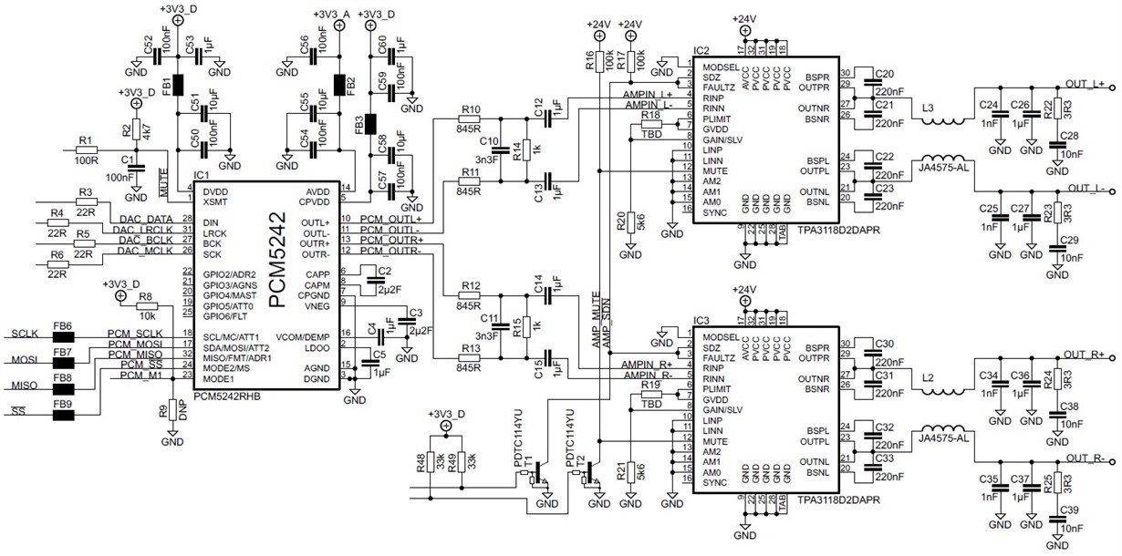
    sorry for this delayed replay, here is the current schematic:

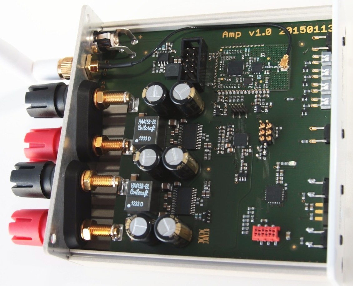
  • and this is the amplifier inside:

  • so, you can see the environment is quite noisy (PurePath Wireless...) therefore I would like to keep the audio path as low impedance as possible.

    The amp works great at the moment but I think it is still not the best I can have from the chipset :) The amp itself, has the idle noise below 50µV RMS A-weighted but fed from the codec it goes up to over 150µV... :( You can take a look on the design and I would be glad to having from you any suggestion how to optimize audio performance.

    Best regards,
    Tomasz
  • Hi Ti experts,

    any tips, tricks or just some suggestions how to get the best noise performance from this design?

    Cheers,

    Tomasz

  • Tomasz

    have you done a signal-chain noise gain calculation?

    you get 50uV from the AMP itself - fine, is that witht he DAC muted?

    the 150uV is that with the wireless link running - then it coudl be the link adding the noise - with 20db gain in the AMP the dac+signal chain before that needs need to have less than 25uV/10=2.5uV noise not to increase the output noise - the noise sources sum with RSS if they are un-correlated

    rgds,

    kim

  • Hi Kim,

    sorry for my delayed replay, I measured the noise one more time.

    The noise below 50µV RMS A-weighted it the idle noise of my TPA3118D2 amplifier itself - without any source. The Amplifier input is open during this measurement.

    The complete audio chain I measured:

    digital source -> PurePath Wireless Transmitter -> PurePath Wireless receiver -> PCM5242 -> RC filter / attenuator -> TPA3118D2 loaded with 4R resistive load (receiver as on the schematic diagram showed before).

    What I measure is:

    Case 1. The PurePath Wireless receiver gets no data (transmitter switched off), the PCM5242 is automatically muted - the output noise is < 105µV RMS (~74µV RMS A-weighted).

    Case 2. The digital source sends digital zeros, PurePath Wireless receiver gets the zero data and send the correct I2S signals to PCM5242. The output noise increases to about 118µV RMS (~82µV RMS A-weighted)

    The amplifier gain is set to 20dB and the RC filter / attenuator sets the amplifier maximal output signal @ 0dBfs at 15V RMS. The results are very good because muted amplifier has SNR > 105dB and unmuted SNR is > 102db :)

    now the questions:

    1. the output noise is: the 50µV amplifier idle noise + 10x amplifier input signal (PCM5242 noise) - (10x 2.5µV) ??? There is no idle noise defined for PCM5242 in the d/s...

    2. could you tell me what is the idle noise of the PCM5242 playing digital zeros? I haven't any reference board with PCM5242 and my reworked PCM5102 board (I placed the PCM5142 on it) is at the moment not working :( This is why I cannot perform any reference measurement... Could you tell me what would be the idle noise with filtered out of band noise using my RC filter / attenuator?

    3. is the output noise a sum of the amplifier idle noise (open input) and the input noise?

    Thanks,
    Tomasz