This thread has been locked.

If you have a related question, please click the "Ask a related question" button in the top right corner. The newly created question will be automatically linked to this question.

TAS5548 EVM external I2C configuration and supply

Other Parts Discussed in Thread: TAS5548

Hello,

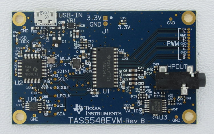
I have a TAS5548EVM and would like to supply the board from an external 3,3V voltage source. Is it ok to remove R28 to disconnect the on-board regulator to do this?

Furthermore, I would like to configure the TAS5548 via an external I2C-Master. Removing R9 will keep the TAS1020 in reset state, which should disable its I2C pins. 

Are both measures sufficient for external supply and configuration of the board, or did I overlook something? 

Thanks and regards,

Stephan

  • Hi Stephan,

    If you see J1 on the middle top of the board, you can use this for external 3.3V source.  You don't need to remove R28.  The square pad is the (+) and the round pad is the (-).  Just be sure that the source is 3.3V.

    Thanks,

    Tuan

  • Hi Tuan,

    thanks for the information. I thought I had to disconnect the onboard regulator to avoid a clash of its output with the external supply, even if USB is not connected.

    For the connection of an external I2C-master it is sufficient to keep the TAS1020 in reset?

    Best regards,

    Stephan 

  • Hi Stephan,

    Since you are not driving I2S and I2C with TAS1020B, I assume that you have an external source.  It should be okay for TAS1020B in reset.  R14 (CRESET) drives TAS5548 EVM reset pin.  You'll need to de-assert this pin for TAS5548 to work.  So you'll have to de-populate all the I2S signal series resistors.

    Thanks,

    Tuan

  • Hi Tuan,

    thanks for your answer. I tried keeping the TAS1020 in reset, but unfortunately the I2C-pins and reset are then driven low, so I can't program the TAS5548 from an external I2C-master.

    What I found out is, that when the USB is plugged in (even an USB charger works), the TAS1020 seems to start up and then releases the I2C pins, which makes them usable by an external master. In fact, that's very useful, because you can access the I2C via USB and via an external master at the same time without changing something on the board, as long as they are not transmitting simultaneously. Additionally the TAS1020 sets reset high, so you don't need an external connection for it.

    The drawback is, that you need an external USB connection. Is there a way to simulate this, e.g. by pulling the +5V-USB pin to 5V?

    Best regards,

    Stephan