This thread has been locked.

If you have a related question, please click the "Ask a related question" button in the top right corner. The newly created question will be automatically linked to this question.

TAS5760EVM

Hi

I am designing a board we plan to connect directly to the TAS5760EVm for a demonstration / proof of concept.

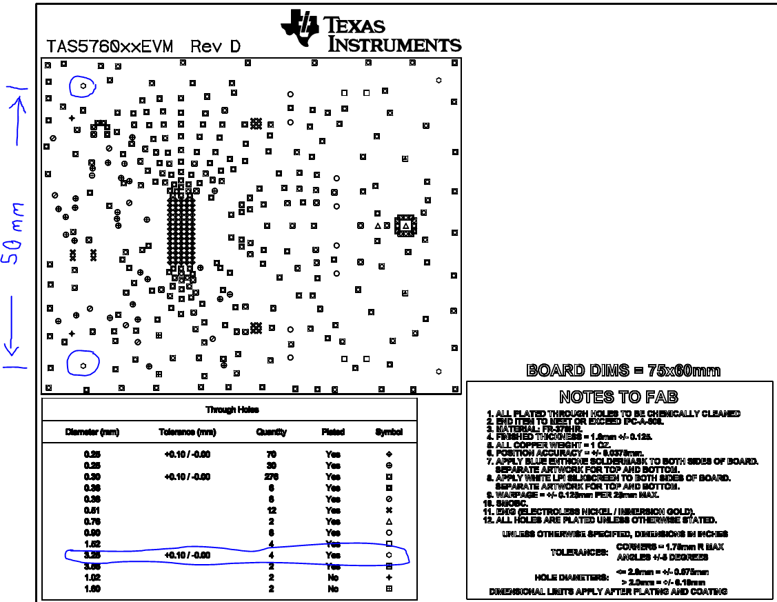
Anyone know where to find the mechanical dimentions on the TAS5760 board? Most important is the 2 screw holes and the big connector.

THX in adwance

Karrsten 

RTX 

  • Hello Karsten, 

    Welcome to E2E, thanks for your interest in our products!. You can get the gerber files of the TAS5760EVM from the product folder of the device:

    http://www.ti.com/tool/tas5760xxevm 

    Best Regards,

      -Diego Meléndez López
       Audio Applications Engineer

  • Hello Diego


    Gerber files does not contain informations enough to measure the midding information. It is a bit veird that TI does not provide this information in the user manual for the TAS amplifier - it is a valuable information to be able to plave holes and connector correct for conection with ab interface board - definetly not what I expected.


    Kind regards


    Karsten Mentz

    (A0389012)


    Diego Meléndez skrev den 2015-05-12 16:14:


    A Message from the TI E2E™ Community
    Texas Instruments


    Diego Meléndez replied to TAS5760EVM.


    Hello Karsten, 


    Welcome to E2E, thanks for your interest in our products!. You can get the gerber files of the TAS5760EVM from the product folder of the device:

    http://www.ti.com/tool/tas5760xxevm 


    Best Regards,


      -Diego Meléndez López
       Audio Applications Engineer


    You received this notification because you subscribed to the forum.  To unsubscribe from only this thread, go here.

    Flag this post as spam/abuse.

  • Hello Karsten,

    The gerber files should have information. It what's used to build the boards. Here's some info on the screws for the connector. The hole diameter is 3.25mm and the spacing between the two are 50mm. They are centered around the connector. They are not critical, but they provide stability for a more robust connection.

  • Hello TI


    So far so good.

    My initial question was distanve between connector AND skrew holes - to be able to place connector and mounting holes on my PCB. The connector to get electrical connection and mounting holes to obtain a stabel construction.

    These informations is needed to get tha board up and running and it is still a big question to me why this not is mentionen in the userguide - a relative simple mechanical drawing.

    Kind regards

    Karsten


    Damian Lewis skrev den 2015-05-12 17:52:


    A Message from the TI E2E™ Community
    Texas Instruments


    Damian Lewis replied to TAS5760EVM.


    Hello Karsten,

    The gerber files should have information. It what's used to build the boards. Here's some info on the screws for the connector. The hole diameter is 3.25mm and the spacing between the two are 50mm. They are centered around the connector. They are not critical, but they provide stability for a more robust connection.


    You received this notification because you subscribed to the forum.  To unsubscribe from only this thread, go here.

    Flag this post as spam/abuse.