This thread has been locked.

If you have a related question, please click the "Ask a related question" button in the top right corner. The newly created question will be automatically linked to this question.

Read-only AGC gain flag is out of range, ADC gain flag is wrong?

I'm trying to setup the AGC on the AIC320TLV3206 and it seems to do nothing except immediately attenuate the signal and then never change after that regardless of input level.

When I investigate, several registers have unexpected values:

  1. The read-only AGC Gain Flag (page 0, reg 93) reads as 11100111 (or -12.5dB) which is outside and below the specified range of 1110 1000 to 0111 0100. The AGC is supposed to only reduce gain by as much as -12dB. How does this register ever get to  11100111?

  2. Even though the AGC Gain Flag reports negative gain, the ADC Fags register (page 0, reg 36) bits D5 and D1 are set indicating that the AGC gain is at the maximum allowed by the Max AGC Gain setting. This is obviously not the case because I read the Max AGC Gain (page 0, reg 93) and it is 0111 0100. 

  3. How can the ADC Gain Status flag be set when the AGC Gain is negative and below the Max AGC Gain?

  4. I have adjusted the noise threshold to very high and very low and the noise flag never gets set.

When I disable the AGC, the analog bypass works well is is loud but when I enable it, the volume is very much attenuated.  The PGA Gain setting (page 0, reg 59) remains unchanged with or without the AGC on. 

My setup is as follows:

  • Analog bypass with a mic connected to IN1 ==> PGA ==> Mixer Amp ==> Headphone Amp
  • ADC is powered on at a 31.25kHz sample rate

I initialize the codec like this:

  1. Reset
  2. Setup power and clocks
  3. Setup the AGC
  4. Setup and power on the ADC
  5. Configure the signal routing and coupling
  6. Set gains on PGA, MA, and analog Volume

These are the AGC settings:

    agc1.enabled = 1;
    agc1.target = 0; // 0 ~ 7 = -5.5 ~ -24.0dBFS
    agc1.gain_hysteresis = 0; // 0 ~ 3 = 0.5dB ~ 1.5dB
    agc1.rsvd = 0;
    agc2.hysteresis = 0; // 0 ~ 2 = 1dB - 4dB, 3 = disabled
    agc2.noise_threshold = 0; // 0 ~ 31 = -30dB ~ -90dB
    agc2.rsvd = 0;
    agc3.max_gain = 0b1110100; // 0b1110100 = 58dB
    agc3.rsvd = 0;
    agc4.attack_time = 0; // 0 ~ 31 = 1 ~ 63*ticks
    agc4.attack_time_scale = 0; // 0 ~ 7 = 1 ~ 128
    agc5.decay_time = 0; // 0 ~ 31 = 1 ~ 63*ticks
    agc5.decay_time_scale = 0; // 0 ~ 7 = 1 ~ 128
    agc6.noise_debounce = 0;
    agc6.rsvd = 0;
    agc7.signal_debounce = 0; 
    agc7.rsvd = 0;

Do you have any suggestions for other things to check? Is is possible to tell if the ADC is even setup properly?

Thanks very much for your help!

  • Hi Noland,

    Thank you for the information that you provided.

    Have you configured another gains in the Codec such the input level or the output level gains? It could be better to have a better approach of this issue.

    Thank you.

    Best regards,

    Luis Fernando Rodríguez S.

  • Thanks for your quick response!

    I'm not sure what you mean by "input level and output level gains". Can you please explain exactly what gains and what registers you are talking about? I have configured the MIC PGA gain, the Mixer Amp gain, and the Headphone Amp gain. What other gains do you mean?

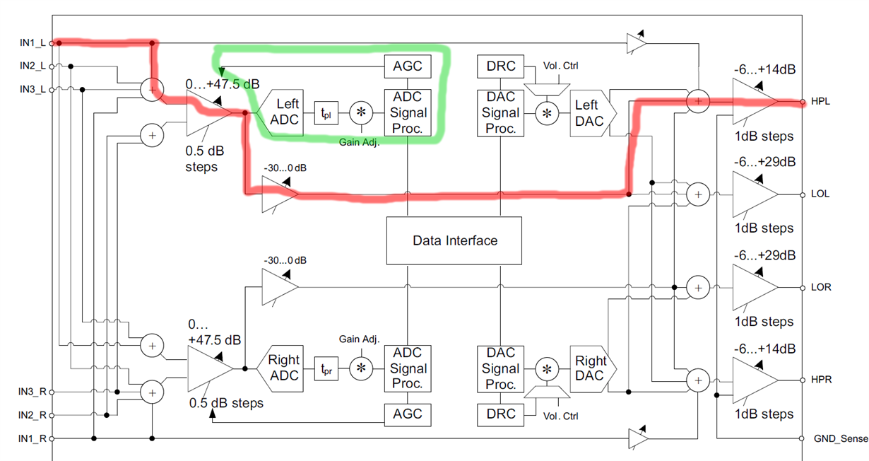
    When the AGC is disabled, the system works as expected. When the AGC is enabled, I expect the gain of the MIC PGA amp to be increased or decreased depending on the mic input level but this is not happening. What happens is the output is attenuated and the saturation flag is set even though the AGC gain is less than max gain and the AGC gain flag is outside the range specified that it can be in by the datasheet. Is this some sort of undocumented error state?

    Please see my diagram below. The red line is the signal path. The green line is the AGC and ADC system I am trying to use.

    Thanks very much for your help!

  • Hi Noland,

    Thank you for provide more information about your application.

    I would like to know the values of the gains that you're using in the red path that your marked. Could you provide the values that you configured for the MICPGA gain, the Mixer Amp Gain and the Headphone Amp Gain? These values could be related with this unexpected behavior. Have you tried to use the AGC function with all this gains configured at 0dB?

    Thank you.

    Best regards,

    Luis Fernando Rodríguez S.

  • Thanks for digging deeper on this. Sorry for the delay, was on vacation for a bit.

    The MICPGA gain I have set at +47.5dB (page 1, reg 59 = 11011111). I've also tried other gains like 20dB and I've tried not writing to it at all and leaving the default 10000000 (0dB)

    The Mixer Amp volume I set at 0.0dB (page 0, reg 24 = 00000000).

    The Headphone Amp I have set to +14dB (page 1, reg 16 = 00001110).

    I don't understand how the Headphone Gain or the Mixer Amp gain can affect the AGC, can you please explain?

    Am I supposed to set the MICPGA gain manually to some special value to allow the AGC to control it?

    Thanks for your help!

  • Hi Noland,

    Don't worry about the delay. There's no problem.

    I mentioned these gain blocks because the AGC can only amplify the signal by itself. I made some tests and I could see that the only way to reduce the signal by the AGC is adding an attenuation gain in your signal path.

    Have you configured any negative gain in your signal path? Could you try placing all the gains in 0dB just to see the AGC effect in your signal?

    Thank you.

    Best regards,

    Luis Fernando Rodríguez S.

  • I have tried several different gains in the signal path. I have tried setting the mixer amp volume to 0, -30 and other values. I tried setting the HP amp to 0 and other values. I tried many different values for the PGA including 0.

    Can you please clarify what you mean? How could the mixer amp affect the AGC? How could the Headphone Amp affect the AGC?

    When the AGC is disabled, I hear the sounds very well and adjusting all the gains works as expected. When the AGC is enabled, the following happens:

    • I don't change any other setting except to enable the AGC and the output volume drops a lot--very attenuated, sounds like the PGA gain is 0
    • AGC target is as high as possible, -5.5dBFS
    • AGC noise flag is not set (AGC does not detect silence)
    • AGC gain is read as 1110 0111 which is out of range and not described in the datasheet! what does this mean?
    • ADC overflow flag is not set
    • AGC gain saturated flag is set. Why? the signal is attenuated below the target and the max PGA gain is not reached. This flag should not be set?
    • PGA gain equal to programmed gain is not set
    • PGA gain remains unchanged from the value I give it--even if that's 0 or 47dB

    Can you please explain why the AGC gain flag is reading an undocumented value and what this value means?

    Can you explain when the gain saturated flag should and should not be set?

    Thanks a ton for your help!

    Noland

  • Hi Noland,

    Sorry for the late response. I made some tests and these are the results.

    • The signal is attenuated due to the target level. So, if your configuration is -5.5dB, you must expect a signal around this value. You may make a test changing the target level to ensure that the signal level is related with this value. If you are searching for amplify the signal, you may try with the different output gains.
    • The noise flag is not activated because your signal must be over the noise threshold.
    • The MICPGA volume control register doesn't affect the AGC gain even if you change the volume value. The volume control register value will be the same when the AGC is enabled, but the gain will be controlled by the AGC.

    Regarding your last questions:

    Can you please explain why the AGC gain flag is reading an undocumented value and what this value means?

    I think it could be related with a mistake in the datasheet. The minimum AGC gain could be -12.5dB. I will search more information about this.

    Can you explain when the gain saturated flag should and should not be set?

    The saturated flag is set when the minimum or maximum AGC gain is reached. It seems that the AGC is reaching the minimum gain (-12.5 dB in this case). I made a test reaching both values (min and max). In two cases, the flag was set.

    I hope this helps you. If you still have questions, please let me know.

    Best regards,

    Luis Fernando Rodríguez S.

  • Thanks so much for the clear and thorough answers, very appreciated.

    Something still seems inconsistent to me though. Why is the gain saturated at minimum but the signal level very low? If if I input silence (the input grounded) the AGC gain remains at -12.5dB and the noise flag is not set. This tells me that the AGC thinks there is signal there to amplify up to -5.5dB but it's not applying any gain to do so.

    Essentially: the AGC gain and saturation flag don't change when I apply silence or loud input or anything in between. It's stuck at -12.5dB gain.

    Can you tell me where my reasoning is wrong here? If the input is low, like way below -5.5dBFS, the AGC should apply positive gain to the PGA to increase the signal level. Correct? (I know I can't read the PGA gain in that register but at least the AGC gain should not read -12.5 and the output should be louder).

    Right now, the output is loud for mic input if I disable the AGC and set the PGA gain to 20.  As soon as I enable the AGC, it drops the PGA gain to what sounds like 0dB gain. Why?

    "If you are searching for amplify the signal, you may try with the different output gains."

    What do you mean by this? I expected the PGA to amplify the signal (and it does when the AGC is disabled). I expect to feed an electret mic into the PGA and output through the mixer amp to the HP amp. This works without the AGC but with the AGC, the PGA does not amplify.

    Thanks for your help!

    Noland

  • Hi Noland,

    Sorry for the late response. I already made more tests with the AGC.

    I input silence (input grounded) and it seems that the flags have a different behavior. I mean, the noise flag is activated and the AGC gain is at maximum (58 dB).

    All your reasoning is correct, the AGC must increase the input if it is less than -5.5dBFS. So, maybe there's a mistake in the rest of the register settings. Could you provide the entire register configuration please?

    Additionally, regarding your last question, I mean that the AGC output can be amplified with an output gain such HPL gain. It could increase the output if the AGC level is too small for you.

    I hope this helps you. If you still have questions or comments, please let me know.

    Best regards,

    Luis Fernando Rodríguez S.

  • Yeah, I'm not seeing the flags the way you are. I think I have a register setting wrong but I can't figure it out. I have recorded the commands sent by the eval board and tried to follow the same sequence. Format is (page, register, data). Maybe there's a sequence wrong? Or a clock setting NADC/MADC is wrong? I can't figure it out. Any help would be hugely appreciated. Thanks so much!

        0x00,   0x04,   0b00000000, // MCLK = CODEC_CLKIN = 16MHz
        0x00,   0x05,   0b00010001, // PLL powered down, PLL P and R values, not used
        0x00,   0x06,   0b00010000, // PLL J value, not used
        0x00,   0x07,   0b00000000, // PLL D MSB value, not used
        0x00,   0x08,   0b00000000, // PLL D LSB value, not used
        0x00,   0x0B,   0b10000010, // NDAC powered up = 2
        0x00,   0x0C,   0b10001000, // MDAC powered up = 8
        0x00,   0x0D,   0b00000000, // DOSR = 512
        0x00,   0x0E,   0b10000000, // DOSR = 512
        0x00,   0x12,   0b10000001, // NADC powered up = 1
        0x00,   0x13,   0b10000010, // MADC powered up = 2
        0x00,   0x14,   0b10000000, // AOSR = 128
        0x00,   0x1B,   0b00100000, // Data width = 20 bits
        0x00,   0x3C,   0b00000010, // DAC processing block = PRB_P2
        0x00,   0x3D,   0b00000010, // ADC processing block = PRB_R2
        0x08,   0x01,   0b00000100, // ADC adaptive filtering enabled
        0x2C,   0x01,   0b00000100, // DAC adaptive filtering enabled
        0x01,   0x7C,   0b00000110, // Charge pump clock divide = 6 * 4 = 24 
        0x01,   0x01,   0b00001010, // Charge pump powered up with internal 8MHz osc, AVDD weak link disabled
        0x01,   0x02,   0b00000000, // Analog blocks enabled
        0x01,   0x47,   0b00110010, // Analog inputs power up time = 6.4ms
        0x01,   0x7B,   0b00000101, // Force power-up of reference in 40ms
        0x01,   0x33,   0b01000000, // Mic bias powered up to 1.25V (if CM=0.9V)
        0x01,   0x34,   0b01000000, // IN1L is routed to left +MICPGA with 10k
        0x01,   0x36,   0b01000000, // CM is routed to left -MICPGA with 10k
        0x01,   0x3B,   0b00000000, // Left MICPGA gain enabled
        0x00,   0x51,   0b10000000, // Left ADC powered up
        0x00,   0x52,   0b00001000, // Left ADC un-muted, right ADC muted
        0x01,   0x0C,   0b00001010, // MAL and left DAC routed to HPL
        0x01,   0x0D,   0b00001000, // Right DAC routed to HPR
        0x01,   0x0E,   0b00001000, // Left DAC routed to LOL 
        0x01,   0x0F,   0b00001000, // Right DAC routed to LOR
        0x00,   0x3F,   0b11010110, // DAC channels routed to audio data, soft-stepping disabled
        0x01,   0x7D,   0b00010010, // Ground-centered HP output enabled, DC offset correction enabled
        0x01,   0x10,   0b00001110, // HPL not muted and some gain
        0x01,   0x11,   0b00000000, // HPR not muted
        0x01,   0x12,   0b00000000, // LOL not muted
        0x01,   0x13,   0b00000000, // LOR not muted
        0x01,   0x09,   0b00111110, // HPL, HPR, LOL, LOR, and MAL powered up
        0x00,   0x40,   0b00000000, // DAC not muted
        0x00,   0x57,   0b10011110, // Left AGC hysteresis = 4dB, left AGC noise threshold
        0x00,   0x58,   0b01110100, // Left AGC max gain = 58.0dB
        0x00,   0x59,   0x01010000, // Left AGC attack time and scale factor
        0x00,   0x5A,   0b00000000, // Left AGC decay time and scale factor
        0x00,   0x5B,   0b00001100, // Left AGC noise debounce
        0x00,   0x5C,   0b00000011, // Left AGC signal debounce
        0x00,   0x56,   0b10000010, // Left AGC enabled and target level

  • Hi Noland,

    Please see the attached document. It's about the AGC default configuration that I used in the evaluation board.

    Recorded_Script.txt
    //MCLK = 11.2896MHz; BCLK = 2.8224MHz; WCLK = 44.1KHz
    
    w 30 00 00			//Page 0
    w 30 01 01			//Software reset
    w 30 00 01			//Page 1
    w 30 01 08			//Disabled weak connection of AVDD with DVDD
    w 30 02 00			//Analog Blocks Enabled
    w 30 47 32			//Analog inputs power up time
    w 30 7B 01			//Reference will power up in 40ms when analog blocks are powered up
    w 30 00 00			//Page 0
    w 30 0D 00			//DAC OSR(MSB)
    w 30 0E 80			//DAC OSR(LSB)
    w 30 12 81			//NADC powered up; NADC=1
    w 30 13 82			//MADC powered up; MADC=2
    w 30 0B 81			//NDAC powered up; NDAC=1
    w 30 0C 82			//MDAC powered up; MDAC=2
    w 30 00 01			//Page 1
    w 30 33 78			//MICBIAS configuration register		
    w 30 34 04			//IN3L is routed to left MICPGA(P) with 10k res
    w 30 36 04			//IN3R is routed to right MICPGA(M) with 10k res
    w 30 3B 00 00			//Left MICPGA is enabled
    w 30 00 00			//Page 0
    w 30 51 C0 00			//Left/Right ADCs powered up; Left/Right ADCs unmuted
    w 30 00 00			//Page 0
    w 30 57 9E 2E 50 00 0C 03	//AGC configuration
    w 30 56 C2			//AGC configuration
    

    I used the input IN3 with the board microphone.

    I hope this helps you. If you still have questions, please let me know.

    Best regards,

    Luis Fernando Rodríguez S.