This thread has been locked.

If you have a related question, please click the "Ask a related question" button in the top right corner. The newly created question will be automatically linked to this question.

Galvanostat-Circuit with NE5532

Other Parts Discussed in Thread: NE5532

Hallo,

I'm new to the Ti E2E Community Forum.

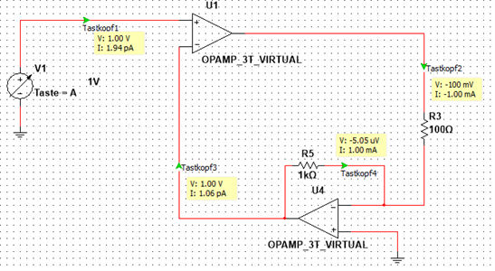
I tried to build a galvanostat-curcuit (figure1) that consists of two components. The Components are a voltage controlled current source to convert the input-voltage into an equivalent voltage and a transimpedance amplifier to convert this current back into a voltage. For this curcuit I used the NE5532 opamp.

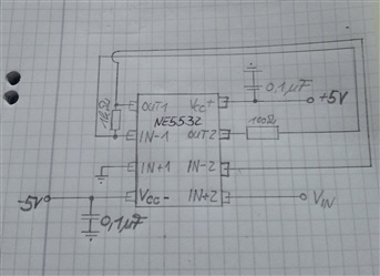
At first I tried to build up the curcuit (figure1) on a board (figure2) to test the dc functionality, but it does not work well. The input-voltage is 1V and the current through the 100 Ohm resistor is 50mA. All other values are also wrong (to high, some of  them max level).

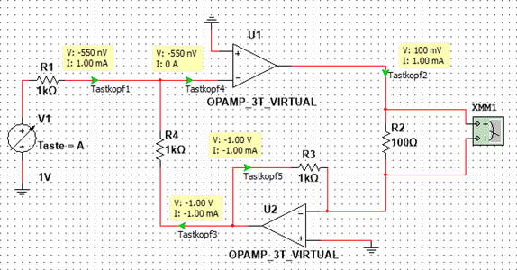
Next, i tried to build up an alterntive circuit (figure3), but the same problem and the output of the opamp oscillate.

I thought all these Problems are caused by instability and therefore i decided to simulate the curcuit to investigate the stability in the bode-plot. I tried to simulate with Qucs but I do not know exactly how to do this with Qucs.

Maybe anyone of you can tell me where my problem lies exactly, and maybe give me a tip for the simulation with Qucs?

Sorry for my very bad english!

Many thanks

Philipp

Figure1

Figure2

Figure3

  • Hi Philipp,

    This is an audio amplifier, I am moving it to the audio amplifier forum.

    Regards,
    Loren
  • Hi,
    Your problem is, that U2 and U4 inverts output signal phase of U1, and as result you got positive feedback instead of needed negative f. for U1. Simplest way for to solve this problem (in Figure 3) would be, if you disconnect U2, R3, R4, and connect R2 direct to U1 inverted input. In this situation you can use other opamp as high impedance input buffer for V1 source.
  • Philipp,

    The NE5532 input and outputs do not operate near the power supply rails. Can you try high supply voltages?
    Also check to make sure outputs do not oscillate.
  • Ron, do you think, that these schematics can work, when U1 gets positive feedback, as shown on pictures? As minimum, needs to interchange U1 inputs, but in this way loop stability maybe a problem on high frequencies. In my opinion, better way I described in my previous post.
  • Victor,

    Your post is correct. U2 inverts and amplifies the U1 output by 10V/V. It is positive feedback at U1 as you stated.
    Switching the input pins at U1 fixes feedback polarity.

    However U2 increases loop gain by 20dB and NE5532 probably doesn't have 20dB of gain margin. Oscillation will be the result.
  • Hi,

    thank you for your feedback.

    I tried to use the NE5532 with higher supply voltage but it doesn't work very well. And you're right a problem is the oscillation.

    Thank you for you're advice, Victor, but i real need the op amp U4 respectively U2. I want to convert the current through R2 into an equivalent voltage because i also want to connect the U2 to an analog/digital converter and therefore i need the U4 respectively U2.

    I understand the problem with positive feedback of the signal phase. I think in order to solve this problem would be the exchange of input pins of the op amp U1 useful, right? (Figure4)

    (Figure4)

    Regards

    Philipp

  • Hi Philipp,
    Yes, U1 input pins on last picture are in right position.
    But, you may also has high frequency oscillations according Ronald's note. For to solve this, you can try resistor around 500 ohms between U1 negative input and ground. Next, please connect capacitor around 100 pF between U1 output and negative input. This would be bypass way for high frequency. Play with new capacitor's nominal, if you do not get acceptable result, or for the best dynamic response of schematic.

    Regards.
  • I'm not familiar with the design of galvanostats but there is a positive feedback loop within your circuit as u2 inverts a fed back signal and then u1 also invert this in the forward path. This will lead to the circuit fulyl saturating at one extreme of operation.

    Regards
    Paul