This thread has been locked.

If you have a related question, please click the "Ask a related question" button in the top right corner. The newly created question will be automatically linked to this question.

Excessive noise on TLV320AIC34 output

Other Parts Discussed in Thread: MSP430F5359, TLV320AIC34

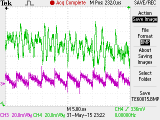
As I've mentioned in previous posts, we are designing a new hardware platform that uses an MSP430F5359 interfaced to the TLV320AIC34 codec using the method described in app note SLAA449A.  I believe we have the design mostly working with respect to the output stage, but I have observed what appears to be rather significant noise on the signal.  In my test setup, I'm trying to send a full scale linear ramp-up/ramp-down signal out through the codec.  Although the signal appears to have the general shape and frequency that I'd expect, there is noise (upwards of 50mv) on the output signal from the codec.  I have the codec configured such that I should be sending new 32-bit samples (16-bit left, 16-bit right) at about a 20khz rate.  This means my samples should be changing roughly once every 50 microseconds.  As you can see from the traces below, the signal noise I'm seeing is far above this frequency.


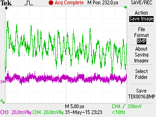
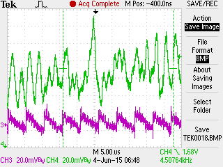
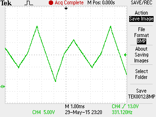
I'm at a loss as to what could be causing the noise.  I've attached three scope traces below.  The first shows the general shape and frequency of my output signal.  It's an alternating triangle wave pattern where I vary the amplitude on every other cycle.  The other traces show a zoomed in view to provide a close inspection of the signal (still in green) and the power supplies (26v and 3.3v) used to power the system and output stage amplifier.  The power supply traces are pink and are ac coupled so you can see the "ripple".  It doesn't look to me as through the noise on the codec output is related to my power supply ripple.  So, I'm not too sure where it is coming from or if there is some other setting within the codec that could be used to improve this signal.


Please let me know what other information you would need from me to further diagnose this issue.

General waveform shape and frequency...

Zoomed in view showing signal (green) and 26v power supply (pink) ac coupled.

Zoomed in view showing signal (green) and 3.3v power supply (pink) ac coupled.

  • Hi Christopher,

    Thank you for provide the scope traces.

    I think it could be related to the signal path in the TLV320AIC34. Could you provide your register configuration or could you describe the signal path that you configured in the codec please?

    Thank you.

    Best regards,

    Luis Fernando Rodríguez S.

  • Hello Luis,

    Here is my register configuration used to set up the Left and RIght outputs for Codec A in the TLV320AIC34:

    Addr   Value  // Reg Name
    0x07 = 0x80   // CDREG_CODEC_DATAPATH_SETUP
    0x09 = 0xF0   // CDREG_AUDSERDATA_ITF_CTRL_B
    0x0A = 0x00   // CDREG_AUDSERDATA_ITF_CTRL_C
    0x03 = 0x91   // CDREG_PLL_PROG_A
    0x04 = 0x10   // CDREG_PLL_PROG_B
    0x05 = 0x00   // CDREG_PLL_PROG_C
    0x06 = 0x00   // CDREG_PLL_PROG_D
    0x0B = 0x01   // CDREG_AUDCODEC_OVFLW_FLGS
    0x02 = 0x22   // CDREG_CODEC_SAMP_RATE_SEL
    0x07 = 0x8A   // CDREG_CODEC_DATAPATH_SETUP
    0x2B = 0x00   // CDREG_LEFT_DAC_DIG_VOL
    0x25 = 0xC0   // CDREG_DAC_PWR_AND_DRVR
    0x52 = 0x91   // CDREG_DACL_2_LEFTL_VC
    0x56 = 0x09   // CDREG_LEFTL_LEVEL
    0x28 = 0x40   // CDREG_HP_OUT_STAGE
    0x07 = 0x8A   // CDREG_CODEC_DATAPATH_SETUP
    0x2C = 0x00   // CDREG_RIGHT_DAC_DIG_VOL
    0x25 = 0xC0   // CDREG_DAC_PWR_AND_DRVR
    0x5C = 0x91   // CDREG_DACR_2_RIGHTL_VC
    0x5D = 0x09   // CDREG_RIGHTL_LEVEL
    0x28 = 0x40   // CDREG_HP_OUT_STAGE

    Please let me know if you require additional clarification or descriptions.

    Thanks,

    Chris

  • Hi Luis,

    I think I may have a clock/pll programming problem. My system is set up using a single 20mhz clock for both my micro and the mclk_x for the codec. As previously described, I'm using the SLAA449A app note to interface my micro to the codec. I am using the 32-bit (16-bits left, 16-bits right) samples. If I am using a 625khz SPI clock to send samples to the codec, that should result in new samples being presented to the codec once every 625khz/32bits = 19.53125 khz. Given this, it seems to me that I need to configure the codec_clk (defined as 256*fs(ref)) to be 256 times the 19.53125khz. Is that correct? Or do I actually need to be targeting a frequency much higher and using the NCODEC (NDAC, NADC) settings to get my update frequency down to the 19.53125khz. I find the documentation somewhat confusing as to what the proper setting should be for these clocks. Any help you can send my way would be greatly appreciated.

    Thanks,
    Chris
  • Hi Chris,

    I reviewed your register configuration.

    As you said, there's a problem in the PLL configuration. There're several conditions that must be reached in order to use the PLL and they cannot be obtained with the MCLK at 20MHz. However, you may try using the MCLK as CLKDIV_CLKIN and configure Q=8. This results in (20MHz)/(128*8) = 19.53125 KHz.

    Additionally, I suggest to change Register 9 from 0xF0 to 0xC0 in order to configure the audio data word length as 16 bits (because each channel represents the word length).

    I hope this helps you. If the problem persists, please let me know.

    Best regards,

    Luis Fernando Rodríguez S.

  • Hello Luis,


    Yes, the change away from the PLL to the simply CLKDIV_CLKIN configuration was one that I found before you replied.  I didn't think of the 32-bit vs. 16-bit change on my own though.  So, I've made both changes.  Although I've seen improvement in the overall large scale wave form, the zoomed in view still shows excessive noise on the signal.  See my latest scope image below.  The Codec signal in green and my 26v power supply ripple in pink:

    I believe both changes were correct and should be made.  However, the original problem of excessive noise remains.  Do you have any other ideas as to what may be causing this?  You originally mentioned something about the signal path in the codec.  Do you still think there's a problem with how I have that set up?

    Thanks again for your help so far.

    Best regards,

    Chris Ingraham

  • Hello Luis,
    I guess for completeness I should mention that the register settings that I've changed since the initial listing I sent you are as follows:
    Addr Value // Reg Name
    0x09 = 0xC0 // CDREG_AUDSERDATA_ITF_CTRL_B
    0x03 = 0x41 // CDREG_PLL_PROG_A

    These to changes should set the audio data word length to 16 bits, turn off the PLL and use a Q of 8 as you suggested.

    Best regards,
    Chris Ingraham
  • Hello Luis,

    I've been doing more investigation on my end and I've found that if I always write "zero" data to the codec, the output remains quite stable around the zero mark as I'd expect.  The "noise" is less than 18mv on the steady state zero signal.  If however I write a steady value of 0x0001 to the channel data (both left and right channels), the noise level jumps up to over 600mv.  I've checked the data being sent and I'm convinced it is correct.  My buffers are all initialized to the value 0x0001 for both channels.

    I dug deeper into the SLAA449A app note and it describes the "Left-Justified" mode the same way the TLV320AIC34 datasheet does.  Specifically, the data sheet states:  "In left-justified mode, the MSB of the right channel is valid on the rising edge of the bit clock following the falling edge of the word clock.  Similarly, the MSB of the left channel is valid on the rising edge of the bit clock following the rising edge of the word clock."

    The SLAA449a app note say exactly the same thing.  Both data sheets follow up that description with a very nice timing diagram showing the relationship of the BCLK and the WCLK signals.  What I find interesting is that in both datasheets, the timing diagrams show the WCLK changing on the falling edge of BCLK.  This seems like a good thing since the left and right channel MSB's are supposed to be valid on the next rising edge of the BCLK following the change in the WCLK.

    Here's the odd thing.  The circuit suggested in the app note, (and the one we've implemented in our design), appears to have the WCLK changing with the rising edge of the BCLK.  This seems a little dangerous to me since it may either cause a race condition or an unexpected bit delay in the data stream.  In the worst case, it would result in inconsistent interpretation of the data being presented at the interface.  Do you think this may be the root cause of the problem?

    Best regards,

    Chris Ingraham

  • Hi Christopher,

    Sorry for the late response.

    Regarding your question about the signal path in codec, in the most part of codecs, there're some paths that generate noise in the outputs. I don't think anymore that it is a path problem, because the lines you're using are DAC_L/R1 and both are connected to the mixer (which has a filter that reduce the noise). The paths DAC_L/R2 and DAC_L/R3 use to generate more noise. You may try using both paths and seeing the difference.

    The noise appears even when the data is transmitted properly. So, I think it could be related to the data serial interface as you said. It could be an inconsistent interpretation of data.

    Additionally, do you have any filter at the codec output? If the noise is of type out-of-band, maybe this document could help you: http://www.ti.com/lit/an/slaa313/slaa313.pdf 

    I hope this helps you. If you still have questions and the problem persists, please let me know.

    Best regards,

    Luis Fernando Rodríguez S.