This thread has been locked.

If you have a related question, please click the "Ask a related question" button in the top right corner. The newly created question will be automatically linked to this question.

VAD with dynamic threshold and hangover period

Hello


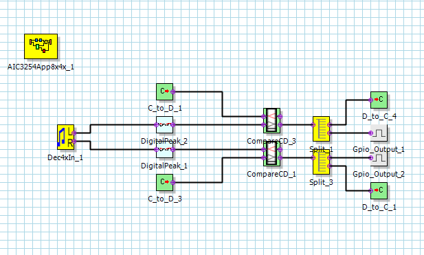
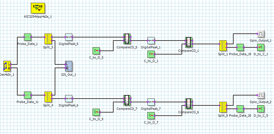
I am going to use PurePath Studio to create a design of a Vox Activation Switch function using a DigitalPeak and a compareCD - like the existing VAD block (see below)  -  but having the VAD_TH_DB setup to be updated at runtime.

  • My question is about the hangover period. Is there a way to do something similar and if yes what would be the most appropriate way.

VAD_TH_DB

Float

VAD Threshold (in dB). The VAD threshold determines the margin between signal power and noise power. If the signal power is higher than the noise power by the given margin, then voice activity has been detected. The recommended range is 3 dB to 9 dB, and the default value is 6 dB. Higher threshold may cause less voice detection in noisy background condition while lower threshold may cause false voice detection in non-stationary background noise.

VAD_HANG_PRD

Float

VAD Hangover Period (in secs.). VAD will remain ON during the hangover period even after signal level gets lower than noise level by threshold margin. Longer handover period will make VAD ON-OFF switching less frequent while VAD will remain ON longer after the end of speech. The recommended value is 0.1 sec to 0.5 sec.

  • Hello,

    Let's say that your goal is to detect a signal and output a '1' once a signal is detected, '0' otherwise. Once the signal is detected you want to keep the output at '1' for some amount x.

    You can use the digital peak component to detect an instantaneous level. Add a comparator afterwards to set the level to '1' if the signal is above threshold level "th1".

    Then after the comparator, add another digital peak. Use the digital peak alpha filter to slow down its release (decay).

    Then have after the second digital peak, add another comparator with a lower threshold "th2".

    Regards,
    J-
  • Thank you for this useful answer. Now - I am definitely not mastering all aspect of PurePath design - especially  how do I get the results coming out of the last comparator?

    Do I need a probe or a another similar block ?

    Even a GPIO as output pin that I could route to the FPGA?

    I am a bit confused on this part. Let me know...

  • Hi,

    The CompareCD component has 2 data outputs. Refer to its help file for detailed information on what each of these outputs do. The outputs are fed to the data memory. You can monitor this by connecting the output to the I2S_Out component or you can convert it to coefficient memory by using a DtoC component (Data to Coefficient). Then you can read the value in coefficient memory by switching buffers and then reading the corresponding coefficient location.

    In the end application, once you know things are working properly, you can use the GPIO Output component (under InputOutput). This will generate an interrupt pulse (not the actual level of the signal) so you still need to read coefficient memory (and use a DtoC component).

    Regards,

    J-

  • Thanks J.. this is really really useful.

    I think I've made good progress so far. Here is my design. (inputs from analog microphones connect to IN1_L/R respectively). Do you see any concern at first sight ?

    Let me know thanks. Your expert advices could save me some precious hours... (hangover is not designed yet.. I will add it later)

    Note that I am using left and right channels (as 2 single mono) independantly . I need one independant VOX function per channel. Is that OK ?


  • Hi,

    Maybe you want to also send that data to I2S_Dout so you can monitor the data in realtime. That will make debugging much easier.

    The hangover period is easy to implement. Just repeat the algorithm again. In the end you will have two time constants.

    Regards,
    J-
  • Thanks Jorge,

    The design is working as expected in the evaluation board, from what can I see on probe chart... 

    But I still have one question.

    As you suggest it I have set a couple of GPIO blocks configured respectively as INT1 for left  channel / INT2 for right channel to externally trigger independantly the coefficient read per channel.

    When I looked at those pins in real-time with a scope there is no difference in phase between INT1 / INT2 (i.e they are similar signals) when I was expecting there are some.. (I use a particular stereo audio file as VOX input with left activity and right activity separated by silences) 

    How do those interrupts works ? Its seems to me as long as there is some audio activity on the channel those bits are toggling. They seems to be toggling even when no code is running on the evaluation board as soon as there is audio activity on the channel.

    So I would like to be sure I have connected those pins correctly so if your can confirm / negate those points..  

    Otherwise I was figuring out if there is any possibility not to use those GPIO's and just do regular poll... on coefficient regs.

    Let me know.  Thanks for your help

  • Hi,

    P0_R48_D2 and R49_D2 configures the INT1 and INT2 interrupts to be miniDSP interrupts. However, miniDSP interrupts are NOT based on what you connect the the GPIO component. If one of them is triggerred, the the miniDSP interrupts will activate for both because there is a single miniDSP interrupt source.

    What you can do is simply wait for an interrupt and then read both D_to_C_1 and D_to_C_2 to determine the source of the interrupt. P0_R48_D0 and R49_D0 control the nature of the interrupt output (pulse vs level). Once an interrupt arrives, you need to read P0_R46 and R47 and also R44 and R45 to clear the interrupt.

    Regards,

    Jorge