I have some PCM4204 parts that are not working correctly.
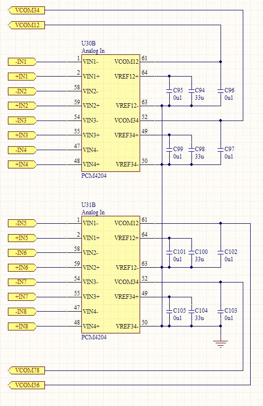
In some cases, both the VREF+ and VCOM are at 0V, others VREF+ is 2.5V but VCOM is 0V.
I have one board out of four that is working correctly where VREF+ and VCOM are at 2.5V.
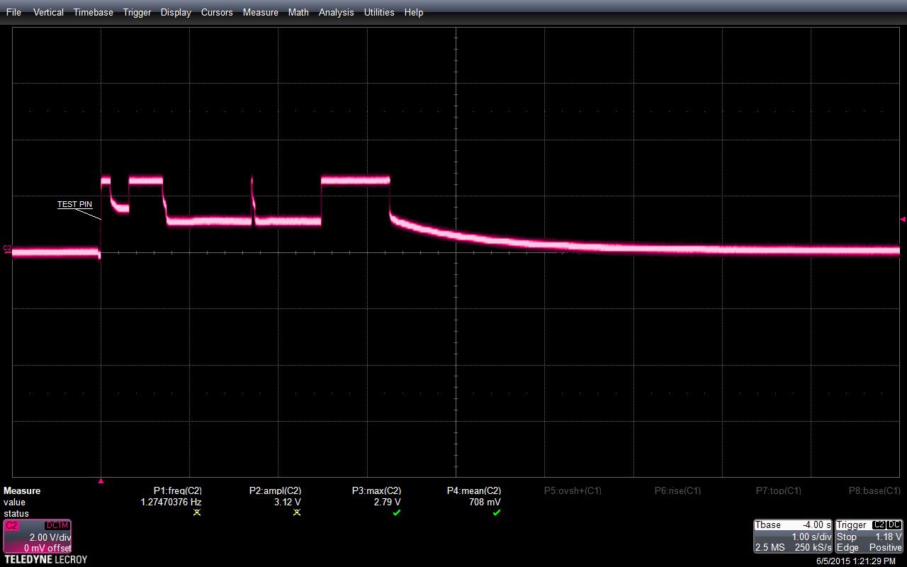
In this design, I do not have the test pin grounded as is recommended. Could this cause the problem for some parts and not for others? What is the test pin used for?
Also, at one point in the development cycle, all the parts were powered by 3.3V on the VDD while the VCC was not powered. I have subsequently fixed this problem but could the parts have been damaged by this condition?