


Hello Everyone,
We are working with I2S interface with TLV320AIC1106 device. The issue is that there is no I2C interface & customer wants to operate in default configuration. I am not sure what the default configuration is.
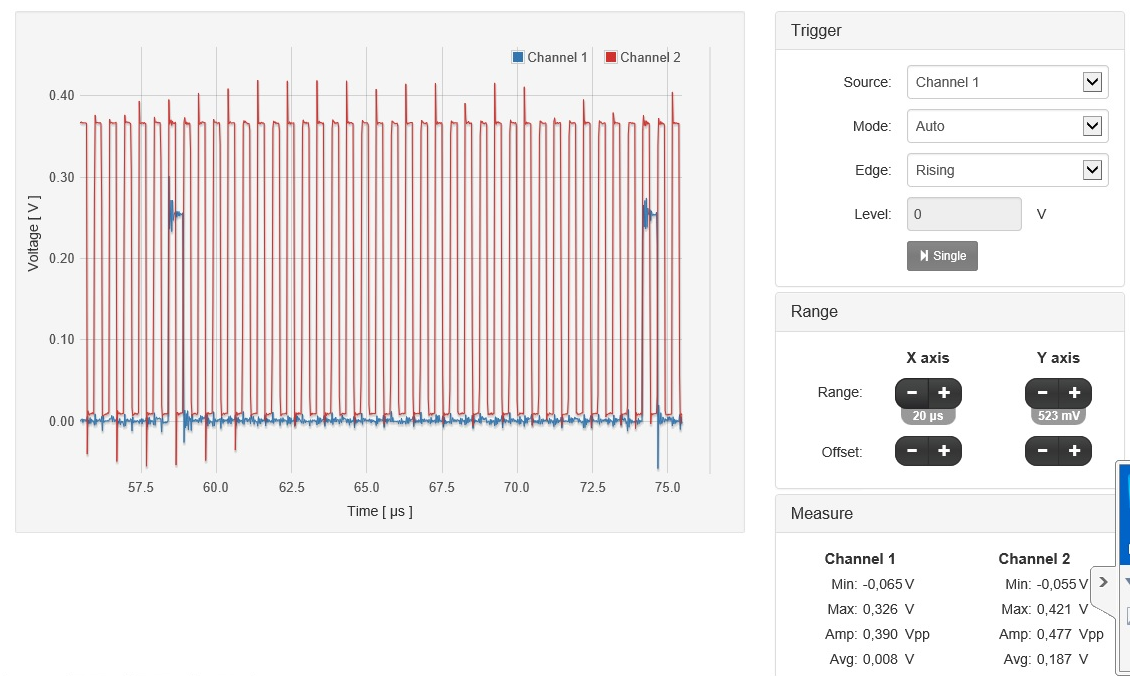
PFA the output on the scope. it shows Clock & sync pulse, data is not available. I had checked data pin separately, it is showing data. Please ignore the voltage levels showed in image below, they are attenuated by 10. The actual voltage is 3.9V for Clock & sync pulse is 3.6V. The sync pulse comes after 32 clock cycles. The output signal looks good & is as per the timing diagram mentioned on page 19 of the datasheet.
There is one issue, the clock is 2.033Mhz not 2.048. I feel that PLL should take care.
I am sending value 20,000 on the I2S out pin from my microcontroller. How to check the output of the TLV ? How to get TLV working ?
Regards,
Chaitannya
