This thread has been locked.

If you have a related question, please click the "Ask a related question" button in the top right corner. The newly created question will be automatically linked to this question.

tlv320aic32x4 capture problem

Other Parts Discussed in Thread: TLV320AIC3254, TLV320AIC3254EVM-K

Hi, 

In our custom board, tlv320aic3254 is used.

We are able to play audio data using aplay, But we are not able to capture the data using mic.

The mic is connected to IN3R line. 

We are using arecord to capture data, "hexdump" of  captured data is '0' as shown below:

root@dra7xx-evm:~# hexdump file.dat

0000000 4952 4646 ee24 0002 4157 4556 6d66 2074
0000010 0010 0000 0001 0002 bb80 0000 ee00 0002
0000020 0004 0010 6164 6174 ee00 0002 0000 0000
0000030 0000 0000 0000 0000 0000 0000 0000 0000
*
002ee20 0000 0000 0000 0000 0000 0000

Register dump of tlv320 is as following:

==============================

root@dra7xx-evm:~# i2cdump -f -y 0 0x18
No size specified (using byte-data access)
0 1 2 3 4 5 6 7 8 9 a b c d e f 0123456789abcdef
00: 00 00 60 00 03 21 08 07 80 00 00 08 02 00 80 02 ..`.?!???..??.??
10: 00 08 08 04 40 01 00 04 00 00 01 0c 00 01 04 00 .???@?.?..??.??.
20: 00 00 00 00 00 00 00 00 00 00 00 00 00 00 00 00 ................
30: 00 00 00 00 00 12 03 02 02 00 00 00 01 01 00 14 .....????...??.?
40: 0c 00 00 00 6f 38 00 00 00 00 00 ee 10 d8 7e e3 ?...o8.....???~?
50: 00 00 00 00 00 00 00 00 02 00 00 00 00 00 00 00 ........?.......
60: 7f 00 00 00 00 00 00 00 00 00 00 00 00 00 00 00 ?...............
70: 00 00 00 00 00 00 00 00 00 00 00 00 00 00 00 00 ................
80: 00 00 00 00 00 00 00 00 00 00 00 00 00 00 00 00 ................
90: 00 00 00 00 00 00 00 00 00 00 00 00 00 00 00 00 ................
a0: 00 00 00 00 00 00 00 00 00 00 00 00 00 00 00 00 ................
b0: 00 00 00 00 00 00 00 00 00 00 00 00 00 00 00 00 ................
c0: 00 00 00 00 00 00 00 00 00 00 00 00 00 00 00 00 ................
d0: 00 00 00 00 00 00 00 00 00 00 00 00 00 00 00 00 ................
e0: 00 00 00 00 00 00 00 00 00 00 00 00 00 00 00 00 ................
f0: 00 00 00 00 00 00 00 00 00 00 00 00 00 00 00 00 ................

root@dra7xx-evm:~#
root@dra7xx-evm:~# i2cdump -f -y 0 0x18
No size specified (using byte-data access)
0 1 2 3 4 5 6 7 8 9 a b c d e f 0123456789abcdef
00: 01 00 00 00 00 00 00 00 00 00 00 10 00 00 00 00 ?..........?....
10: 40 40 40 40 00 00 00 00 00 00 00 00 00 00 00 00 @@@@............
20: 00 00 00 00 00 00 00 00 00 00 00 00 00 00 00 00 ................
30: 00 00 00 00 00 00 00 04 00 00 00 80 80 00 03 00 .......?...??.?.
40: 00 00 00 00 00 00 00 00 00 00 00 00 00 00 00 00 ................
50: 00 00 00 00 00 00 00 00 00 00 00 00 00 00 00 00 ................
60: 00 00 00 00 00 00 00 00 00 00 00 00 00 00 00 00 ................
70: 00 00 00 00 00 00 00 00 00 00 00 00 00 00 00 00 ................
80: 00 00 00 00 00 00 00 00 00 00 00 00 00 00 00 00 ................
90: 00 00 00 00 00 00 00 00 00 00 00 00 00 00 00 00 ................
a0: 00 00 00 00 00 00 00 00 00 00 00 00 00 00 00 00 ................
b0: 00 00 00 00 00 00 00 00 00 00 00 00 00 00 00 00 ................
c0: 00 00 00 00 00 00 00 00 00 00 00 00 00 00 00 00 ................
d0: 00 00 00 00 00 00 00 00 00 00 00 00 00 00 00 00 ................
e0: 00 00 00 00 00 00 00 00 00 00 00 00 00 00 00 00 ................
f0: 00 00 00 00 00 00 00 00 00 00 00 00 00 00 00 00 ................

The device tree entry is as follows:

sound {

compatible = "fsl,imx-audio-tlv320aic32x4";
model = "imx6q-mit-tlv320aic32x4";
cpu-dai = <&ssi2>;
audio-codec = <&codec>;
audio-routing =
"Headphone Jack", "HPL",
"Headphone Jack", "HPR",
"IN3_R", "Mic Jack";
mux-int-port = <2>;
mux-ext-port = <4>;

};

Please help me understaing the issue.

Thaks,

Praveen

  • Hi Praveen,

    I found a script that could help you. It's about an example of a differential microphone configuration.

    The command line is in format w xx xx xx: (write_command, xx_I2C_address, xx_register, xx_data).

    ###############################################
    # On-Board Differential Microphone
    # ---------------------------------------------
    # PowerTune mode PTM_R4 is used for high
    # performance 16-bit audio.
    #
    # For normal USB Audio, no hardware change
    # is required.
    #
    # If using an external interface, SW2.4 and
    # SW2.5 of the USB-ModEVM must be set to
    # HI and clocks can be connected to J14 of
    # the USB-ModEVM.
    #
    # IN3L/R is are routed differentially to the
    # LADC.
    ###############################################

    ###############################################
    # Software Reset
    ###############################################
    #
    # Select Page 0
    w 30 00 00
    #
    # Initialize the device through software reset
    w 30 01 01
    #
    ###############################################

    ###############################################
    # Clock Settings
    # ---------------------------------------------
    # The codec receives: MCLK = 11.2896 MHz,
    # BLCK = 2.8224 MHz, WCLK = 44.1 kHz
    ###############################################
    #
    # Select Page 0
    w 30 00 00
    #
    # NADC = 1, MADC = 2
    w 30 12 81 82
    #
    ###############################################

    ###############################################
    # Signal Processing Settings
    ###############################################
    #
    # Select Page 0
    w 30 00 00
    #
    # Set the ADC Mode to PRB_P1
    w 30 3d 01
    #
    ###############################################

    ###############################################
    # Initialize Codec
    ###############################################
    #
    # Select Page 1
    w 30 00 01
    #
    # Disable weak AVDD in presence of external
    # AVDD supply
    w 30 01 08
    #
    # Enable Master Analog Power Control
    w 30 02 00
    #
    # Select ADC PTM_R4
    w 30 3d 00
    #
    # Set the input powerup time to 3.1ms (for ADC)
    w 30 47 32
    #
    # Set the REF charging time to 40ms
    w 30 7b 01
    #
    ###############################################

    ###############################################
    # Recording Setup
    ###############################################
    #
    # Select Page 1
    w 30 00 01
    #
    # Powerup MIC BIAS
    w 30 33 40
    #
    # Route IN3L to LEFT_P with 10K input impedance
    w 30 34 04
    #
    # Route IN3R to LEFT_M with 10K input impedance
    w 30 36 04
    #
    # Unmute Left MICPGA
    w 30 3b 00
    #
    # Unmute Right MICPGA
    w 30 3c 00
    #
    # Select Page 0
    w 30 00 00
    #
    # Power up LADC/RADC
    w 30 51 c0
    #
    # Unmute LADC/RADC
    w 30 52 00
    #
    ###############################################

    I hope this helps you. If you still have questions, please let me know.

    Best regards,

    Luis Fernando Rodríguez S.

  • Thanks Luis,

    It is working with the provided configuration.  I was missing following register to set.

    # Route IN3R to LEFT_M with 10K input impedance
    w 30 36 04


    I have one more question.

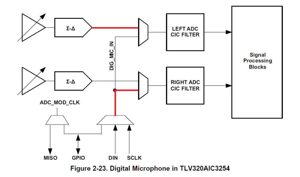
    With TLV320aic3254, A digital mic is also going to connect along with analog mic.

    Since only one I2S port is using for both, then two mics (digital and analog) can work simultaneously? 

    Or at a time only one mic can work?

    Regards,

    Praveen


  • Hi, Praveen,

    I'm glad to hear that the configuration is working.

    Regarding you questions about the microphones configuration, as the 2.3.3.2.2 Digital Microphone Function Section of the TLV320AIC3204 Application Reference Guide mentions, the digital microphone mode can be selectively enabled for only-left, only-right or stereo channels (please see the page 0, register 81: ADC Channel Setup Register for details). In order to use both microphones, it's necessary to configure one of both channels for the digital microphone and the other for the analog microphone (right or left ADC output).

    In the following example, the digital microphone is configured for the right channel and the analog microphone (Left ADC output) is configured for the left channel:

    I hope this helps you. If you still have questions, please let me know.

    Best regards,

    Luis Fernando Rodríguez S.

  • Hi Luis,

    I am able to successfully capture the digital mic data through Left ADC. I set the following configuration:
    p0_r56 : 0x02 /* SCLK is enabled as input for mic */
    p0_r55 : 0x0e /* MISO is clkout for digital mic */
    p0_r81 : 0xd8 /* SCLK serves as Digital Microphone Input, Left ADC configured */

    But I am not able to capture through the Right ADC. I disabled the Left ADC & set the digital mic data routing to Right ADC.
    p0_r81 : 0xd4 /* SCLK serves as Digital Microphone Input, Right ADC configured*/
    p0_r56 : 0x02 /* SCLK is enabled as input for mic */
    p0_r55 : 0x0e /* MISO is clkout for digital mic */

    But all data is 0.

    Even I tried to route Analog mic data to the Right ADC, by commenting out the p1_r34 & p1_r36 values & setting the following registers:

    p1_r37 : 0x4
    p1_r39 : 0x4

    In this case also, all data is 0.

    Am I missing some configuration for Right ADC? Please help.

    Thanks & Regards,
    Praveen

  • Sorry, I got the problem.
    The above configuration is fine. problem was in my driver.

    Regards,
    Praveen
  • Hi Luis,

    I am checking with "Headset detection".

    As mentioned in "tlv320aic3254 application reference guide", I am enabling headset detection in page0, reg67 as following

    P0_R67 :     0x80

    On insertion/Removal of headset, I am checking the value of P0_R44, P0_R46 & P0_R67.

    But I am not getting the expected values on the registers.

    Is this the correct way for headset detection? Please let us know.

    Thanks,

    Praveen

  • Hi Praveen,

    The datasheet mentions at the end of the 2.11.1 Headset Detection Section that the Master Analog Power control in Page 1, Register 2, D3 must be enabled. Have you tried with this?

    Please let me know if the problem persists.

    Best regards,

    Luis Fernando Rodríguez S.

  • Yes Luis, I am trying with the Master Analog power control enabled.

    P1_R2 = 0x0

    The issue persists.

    Meanwhile, I started facing one more issue.

    Till now, Analog Mic was working fine. But now I am seeing strange behaviour.

    I am recording using "arecord", but while playing using "aplay" I am getting only noise. Without doing anything & any delay, I use again arecord/aplay command to capture/play the data. This time I heard proper data without any issue. 

    If I leave the board again for sometime and perform capture/play, Again I get the noise.

    In summary, If I perform two capture(one by one) without delay, The second captured sample has proper data. If i am giving delay between two captures, then noise is captured in both samples.

    I hope I am clear in explaining the issue. Please let me know if I am unclear.

    Thanks,

    Praveen

  • Hi Praveen,

    I apologize for the late response.

    Could you try reading the register configuration when the noise appears and when the device works correctly? It's just to compare the registers and be sure that they are programmed correctly.

    Thank you.

    Best regards,

    Luis Fernando Rodríguez S.

  • Hi Luis,

    After setting  p1_r0x47 and p1_r0x7b registers properly, the noise is gone.

    Could you help us regarding the mic detection? I enabled the mic detection with analog power control enable. But register p0_r67 always shows as 0xa0 whether mic is connected or not. I tried with different type of mics(stereo, stereo + cellular) but no change.

    Should we  require something to take care at hardware level?

    Thanks,

    Praveen 

  • Hi Praveen,

    Please see the attached script. It's an example of the Headset Detection in the TLV320AIC32x4EVM.

    # Page 0
    w 30 00 00
    #
    # Software Reset
    w 30 01 01
    #
    # Page 0
    w 30 00 00
    #
    # NDAC/MDAC powered up; NDAC = 1; MDAC = 2
    w 30 0B 81 82
    #
    # NADC/MADC powered up; NADC = 1; MADC = 2
    w 30 12 81 82
    #
    # Page 0
    w 30 00 00
    #
    # DAC Signal Processing Block PRB_P1
    w 30 3C 01
    #
    # ADC Signal Processing Block PRB_R1
    w 30 3D 01
    #
    # Page 1
    w 30 00 01
    #
    # Disabled weak connection of AVDD with DVDD
    w 30 01 08
    #
    # Analog Blocks Enabled
    w 30 02 00
    #
    # Analog inputs power up time is 6.4ms
    w 30 47 32
    #
    # Reference will power up in 40ms when analog blocks are powered up
    w 30 7B 01
    #
    # Page 1
    w 30 00 01
    #
    # MICBIAS powered up; MICBIAS = 2.075V or 2.5V
    w 30 33 60
    #
    # IN3L is routed to Left MICPGA with 10k resistence
    w 30 34 04
    #
    # CM is routed to Left MICPGA via CM1L to 10k resistence
    w 30 36 40
    #
    # Left MICPGA Gain is enabled; Volume control = 0.0dB
    w 30 3B 00
    #
    # Page 0 
    w 30 00 00
    #
    # Left Channel ADC is powered up
    w 30 51 80
    #
    # Left ADC Channel Un-Muted
    w 30 52 08
    #
    # Page 1
    w 30 00 01
    #
    # Headphone ramps determined with 6k; Headphone ramp power up 
    # in 5 time constants
    w 30 14 25
    #
    # Left/Right channel DAC reconstruction filter's positive
    # terminal routed to HPL/HPR
    w 30 0C 08 08
    #
    # HPL/HPR is powered up
    w 30 09 30
    #
    # HPL/HPR is not muted (0dB)
    w 30 10 00 00
    #
    # Page 0
    w 30 00 00
    #
    # Left/Right DAC volume = 0dB
    w 30 41 00 00
    #
    # Left/Right DAC powered up; Left/Right DAC to Left/Right Channel
    # Soft-Stepping is disabled
    w 30 3F D6
    #
    # Left/Right DAC not muted
    w 30 40 00
    #
    # Page 0
    w 30 00 00
    #
    # Headset Detection Enabled
    w 30 43 80
    

    Additionally, the hardware configuration is important too. The instructions to configure the hardware in order to use the headset detection (in the EVM) are in the following picture:

    Please see the Appendix B (TLV320AIC3254EVM Schematic) in the TLV320AIC3254EVM-K User's Guide to have a better approach of the Hardware Configuration.

    I hope this helps you. If you still have questions, please let me know.

    Best regards,

    Luis Fernando Rodríguez S.