This thread has been locked.

If you have a related question, please click the "Ask a related question" button in the top right corner. The newly created question will be automatically linked to this question.

TAS2505 Initialization problems

Other Parts Discussed in Thread: TAS2505

Good day,


I'm using a kl16 cortex m0 MCU from Freescale together with an TAS2505. The audio data is streamed via I2S to the TAS2505 and the configuration data via I2C.

I was following the 4.0.7 Example Register Setup to Play Digital Data Through DAC and Headphone/Speaker Outputs in the slau472.pdf. I can hear some audio coming out of the speaker, but very distorted and not at all like it is supposed to be.

Anyone has a similar experience?


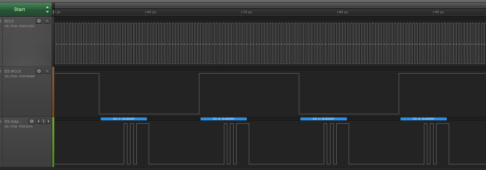
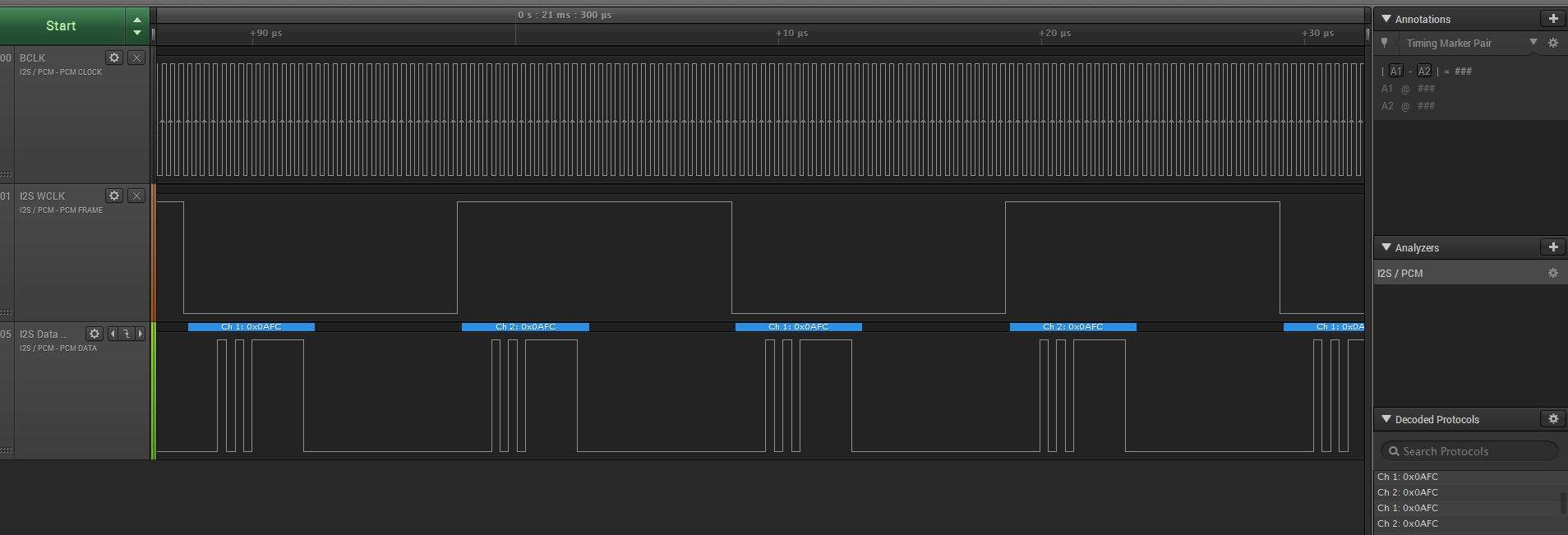
My setup: using digital input with I2S, MCLK from an external source, WCLK and BCLK provided by the TAS2505. WCLK = 44.1 kHz, BCLK = 1.4MHz. 16bit words, 2 word per frame.


Any help or ideas are appreciated.


Regards

Roland

  • Hi Roland,

    Welcome to E2E and thank you for your interest in our products!

    I will take a look at this.
    Are you following line-to-line example 4.0.7?
    Are you able to read the registers you wrote?
    Is there a possibility that the registers are not being written fine?

    Best regards,
    Ivan Salazar
    Texas Instruments
  • Hi Ivan,
    I'm, following the line to line example, but when I do the same initialization order, I cant get any sound output. I can read back all the registers I am writing, so I2C communication is working. Therefore I assume that the register writing is fine.
    How is the output signal supposed to look like? I'm trying to play a 440Hz sine wave and if I measure the speaker inputs with a scope I get a rectangular signal, is that correct?
  • Hi Roland,

    This is a Class-D amplifier so you should see a PWM at the output (SPKP/SPKM). But it seems that your PWM is not modulating so there is no sound.
    Example 4.0.7 configures the device to 16bits, BCLK&WCLK inputs, I2S mode. Are you providing an input like that?
    Could you share a register dump? This is just to compare and discard a register setting problem.

    Regards,
    Ivan Salazar
    Texas Instruments
  • Hi Ivan

    Thanks for the quick reply. I adjusted the specific registers from  the example 4.0.7 so that it fits for my hardware. This includes the BCLK and Frame Sync Direction (set as output). I provide the MCLK from my MCU and have 16 bit wav data from an external flash memory.

    We just bought the TAS2505 Evaluation Kit to rule out a register configuration problem. How does the streaming via USB work? Does the streaming modulate the wav data I play?


    See attached an extract of the .h file with the TAS2505 register settings and the I2S Module settings as well

    Regards

    Roland

    TAS2505registersettings.h

    #define ASM_RESERVED_REG3 0x00 /*  reserved */
    #define ASM_CLK_SETTINGS_REG1_REG4 0x00 /*  Clock Setting Register 1, Multiplexers */        
    #define ASM_CLK_SETTINGS_REG2_REG5 0x11 /*  Clock Setting Register 2, PLL P&R Values */                
    #define ASM_CLK_SETTINGS_REG3_REG6 0x04 /*  Clock Setting Register 3, PLL J Values */            
    #define ASM_CLK_SETTINGS_REG4_REG7 0x00 /*  Clock Setting Register 4, PLL D Values (MSB) */                
    #define ASM_CLK_SETTINGS_REG5_REG8 0x00 /*  Clock Setting Register 5, PLL D Values (LSB) */            
    #define ASM_RESERVED 0x00 /*  reserved */    
    #define ASM_RESERVED 0x00 /*  reserved */
    #define ASM_CLK_SER_NDAC_SETTING_REG11 0x85 /*  Clock Setting Register 6, NDAC Values */        
    #define ASM_CLK_SER_MDAC_SETTING_REG12 0x83 /*  Clock Setting Register 7, MDAC Values */        
    #define ASM_CLK_SER_DOSR_MSB_SETTING_REG13 0x00 /*  DAC OSR Setting Register 1, MSB Value */        
    #define ASM_CLK_SER_DOSR_LSB_SETTING_REG14 0x40 /*  DAC OSR Setting Register 2, LSB Value */        
    #define ASM_RESERVED_REG15 0x02 /*  miniDSP_D Instruction Control Register 1 */                        
    #define ASM_RESERVED_REG16 0x00 /*  miniDSP_D Instruction Control Register 2 */
    #define ASM_RESERVED_REG17 0x08 /*  miniDSP_D Interpolation Factor Setting Register */
    #define ASM_RESERVED 0x00 /*  reserved */
    #define ASM_RESERVED 0x00 /*  reserved */
    #define ASM_RESERVED 0x00 /*  reserved */
    #define ASM_RESERVED 0x00 /*  reserved */
    #define ASM_RESERVED 0x00 /*  reserved */
    #define ASM_RESERVED 0x00 /*  reserved */
    #define ASM_RESERVED 0x00 /*  reserved */
    #define ASM_CLK_SETTINGS_REG10_REG25 0x00 /*  Clock Setting Register 10, Multiplexers */
    #define ASM_CLK_SETTINGS_REG11_REG26 0x81 /*  Clock Setting Register 11, CLKOUT M divider value */        
    #define ASM_AUDIO_INTERFACE_SETTING_REG1_REG27  0x0C /*  Audio Interface Setting Register 1 */
    #define ASM_AUDIO_INTERFACE_SETTING_REG2_REG28  0x00 /*  Audio Interface Setting Register 2 */
    #define ASM_AUDIO_INTERFACE_SETTING_REG3_REG29  0x01 /*  Audio Interface Setting Register 3 */
    #define ASM_CLK_SETTINGS_REG12_REG30            0x82 /*  Clock Setting Register 12, BCLK N Divider */
    #define ASM_AUDIO_INTERFACE_SETTING_REG4_REG31  0x00 /*  Audio Interface Setting Register 4, Secondary Audio Interface */
    #define ASM_AUDIO_INTERFACE_SETTING_REG5_REG32  0x00 /*  Audio Interface Setting Register 5 */
    #define ASM_AUDIO_INTERFACE_SETTING_REG6_REG33  0x00 /*  Audio Interface Setting Register 6 */
    #define ASM_DIG_INTERFACE_MISC_REG34            0x00 /*  Digital Interface Misc. Setting Register */
    #define ASM_RESERVED 0x00 /*  reserved */
    #define ASM_RESERVED 0x00 /*  reserved */
    #define ASM_DAC_FLAG_REG1_REG37 0x80 /*  DAC Flag Register 1 */            
    #define ASM_DAC_FLAG_REG2_REG38 0x11 /*  DAC Flag Register 2 */            
    #define ASM_RESERVED 0x00 /*  reserved */
    #define ASM_RESERVED 0x00 /*  reserved */
    #define ASM_RESERVED 0x00 /*  reserved */
    #define ASM_STICKY_FLAG_REG1_REG42 0xA0 /*  Sticky Flag Register 1 */        
    #define ASM_INT_FLAG_REG1_REG43 0x00 /*  Interrupt Flag Register 1 */        
    #define ASM_STICKY_FLAG_REG2_REG44 0x00 /*  Sticky Flag Register 2 */        
    #define ASM_RESERVED_REG45 0x00 /*  Sticky Flag Register 3 */        
    #define ASM_INT_FLAG_REG2_REG46 0x00 /*  Interrupt Flag Register 2 */        
    #define ASM_RESERVED_REG47 0x00 /*  Interrupt Flag Register 3 */        
    #define ASM_INT1_CTRL_REG_REG48 0x00 /*  INT1 Interrupt Control Register */        
    #define ASM_INT2_CTRL_REG_REG49 0x00 /*  INT2 Interrupt Control Register */        
    #define ASM_RESERVED 0x00 /*  reserved */
    #define ASM_RESERVED 0x00 /*  reserved */
    #define ASM_GPIODOUT_CTRL_REG_REG52 0x00 /*  GPIO/DOUT Control Register */    
    #define ASM_DOUT_CTRL_REG_REG53 0x12 /*  DOUT Function Control Register */        
    #define ASM_DIN_CTRL_REG_REG54 0x02 /*  DIN Function Control Register */        
    #define ASM_MISO_CTRL_REG_REG55 0x02 /*  MISO Function Control Register */        
    #define ASM_SCLK_CTRL_REG_REG56    0x02 /*  SCLK/DMDIN2 Function Control Register */    
    #define ASM_RESERVED 0x00 /*  reserved */
    #define ASM_RESERVED 0x00 /*  reserved */
    #define ASM_RESERVED 0x00 /*  reserved */
    #define ASM_PAGE0_DAC_INSTR_SET_REG60 0x01 /*  DAC Signal Processing Block Control Register */        
    #define ASM_RESERVED 0x00 /*  reserved */
    #define ASM_RESERVED 0x00 /*  miniDSP_D Configuration Register */
    #define ASM_DAC_CHANNEL_SETUP_REG1_REG63 0xB2 /*  DAC Channel Setup Register 1 */
    #define ASM_DAC_CHANNEL_SETUP_REG2_REG64 0x04 /*  DAC Channel Setup Register 2 */
    #define ASM_DAC_CHANNEL_DIG_DAC_VOLUME_REG65 0x00 /*  Left DAC Channel Digital Volume Control Register */
    #define ASM_RESERVED_REG66 0x00 /*  Right DAC Channel Digital Volume Control Register */
    #define ASM_RESERVED_REG67 0x00 /*  reserved */
    #define ASM_RESERVED_REG68 0x6F /*  reserved */
    #define ASM_RESERVED_REG69 0x38 /*  reserved */
    #define ASM_RESERVED 0x00 /*  reserved */
    #define ASM_RESERVED 0x00 /*  Beep Generator Register 1 */
    #define ASM_RESERVED 0x00 /*  reserved */
    #define ASM_RESERVED 0x00 /*  Beep Generator Register 3 */
    #define ASM_RESERVED 0x00 /*  Beep Generator Register 4 */
    #define ASM_RESERVED_REG75 0xEE /*  Beep Generator Register 5 */                    
    #define ASM_RESERVED_REG76 0x10 /*  Beep Generator Register 6 */                     
    #define ASM_RESERVED_REG77 0xD8 /*  Beep Generator Register 7 */                     
    #define ASM_RESERVED_REG78 0x7E /*  Beep Generator Register 8 */                     
    #define ASM_RESERVED_REG79 0xE3 /*  Beep Generator Register 9 */                    
    #define ASM_RESERVED_REG80_TO_REG127 0x00 /*  reserved */            

    /* Page 1 Settings */
    #define ASM_RESERVED_REG0 0x01  /* Page Select Register */                        
    #define ASM_REFPOR_CTRL_REG_REG1 0x10 /* REF, POR & LDO BGAP Control Register */                
    #define ASM_LDO_CTRL_REG_REG2     0x05 /* LDO Control Register */                
    #define ASM_PLAYBACK_CONFIG_REG_REG3 0x24 /* Playback Configuration Register 1 */            
    #define ASM_PLAYBACK_CONFIG_REG2_REG4 0x00 /* Playback Configuration Register 2 */
    #define ASM_DMA_DEM_CTRL_REG5 0x00 /* DAC DEM Control */
    #define ASM_RESERVED_REG6 0x00 /* reserved */
    #define ASM_RESERVED_REG7 0x00 /* reserved */
    #define ASM_DACPGA_CTRL_REG_REG8 0x00 /* Common Mode Register */
    #define ASM_OUTPIT_DRIVER_CTRL_REG_REG9 0x00 /* Output Driver, AINL, AINR, Control Register */
    #define ASM_COMMON_MODE_CTRL_REG_REG10 0x00 /* Common Mode Control Register */
    #define ASM_HP_OVERCURRENT_CONFIG_REG_REG11 0x10 /* HP Over Current Protection Configuration Register */
    #define ASM_HP_ROUTING_SELECTION_REG_REG12 0x00 /* HP Routing Selection Register */
    #define ASM_RESERVED 0x00 /* reserved */
    #define ASM_RESERVED 0x00 /* reserved */
    #define ASM_RESERVED 0x00 /* reserved */
    #define ASM_HP_DRIVER_GAIN_SETTING_REG_REG16 0x40 /* HP Driver Gain Setting Register */
    #define ASM_RESERVED 0x00 /* reserved */
    #define ASM_RESERVED 0x00 /* reserved */
    #define ASM_RESERVED 0x00 /* reserved */
    #define ASM_HP_DRIVER_STARTUP_CTRL_REG20 0x00 /* Headphone Driver Startup Control Register */
    #define ASM_RESERVED 0x00 /* reserved */
    #define ASM_HP_VOL_CTRL_REG22 0x00 /* HP Volume Control Register */
    #define ASM_RESERVED 0x00 /* reserved */
    #define ASM_AINL_VOL_CTRL_SETTING_REG24 0x00 /* AINL Volume Control Register */      
    #define ASM_AINR_VOL_CTRL_SETTING_REG25 0x00 /* AINR Volume Control Register */   

    #define ASM_SPEAKER_AMP_CTRL_REG_REG45    0x02 /* Speaker Amplifier Control 1 */        
    #define ASM_SPEAKER_VOL_CTRL_REG_REG46    0x2B /* Speaker Volume Control 1 */
    #define ASM_RESERVED 0x00 /* reserved */
    #define ASM_SPEAKER_AMP_VOL_CTRL_REG2_REG48    0x10 /*  Speaker Amplifier Volume Control 2 */   

    I2SModuleSettings.c

            #define I2S_WORD_N_WIDTH        31
            #define I2S_WORD_0_WIDTH        31
            #define I2S_SYNC_WIDTH          15
            #define I2S_FBT_SHIFT           I2S_WORD_0_WIDTH
            
            SIM_SCGC6 &= ~(SIM_SCGC6_I2S_MASK);     /* Disable System Clock */
            SIM_SCGC6 |= SIM_SCGC6_I2S_MASK;        /* Enable the clock */
            
            I2S0_TCSR |= I2S_TCSR_SR_MASK;          /* Reset I2S */
            I2S0_TCSR &= ~(I2S_TCSR_SR_MASK);
                                                         
            I2S0_MCR |= I2S_MCR_MOE_MASK;           /* Output MCLK */            

            I2S0_TCSR |= I2S_TCSR_BCE_MASK;         /* Enable Bit Clock */
            
            I2S0_TCR2 |= (I2S_TCR2_BCP_MASK);       /* Set Bit Clock Polarity active low */     
            
            I2S0_TCR3 &= ~(I2S_TCR3_WDFL_MASK);     /* Word Flag Configuration: word 1 sets the start of word flag */
            
    #if I2S_IS_MASTER
            I2S0_TCR2 |= I2S_TCR2_BCD_MASK; /* Bit Clock Direction Output: Master */
            I2S0_TCR4 |= I2S_TCR4_FSD_MASK; /* Frame Sync Direction Output: Master */
    #else
            I2S0_TCR2 &= ~(I2S_TCR2_BCD_MASK); /* Bit Clock Direction Input: Slave */
            I2S0_TCR4 &= ~(I2S_TCR4_FSD_MASK); /* Frame Sync Direction Input: Slave */
    #endif          
     
            /* 2 slot on a frame, Fsynch of 32 clocks */
            I2S0_TCR4 =  (I2S_TCR4_FRSZ_MASK | I2S_TCR4_SYWD(I2S_SYNC_WIDTH)|I2S_TCR4_MF_MASK | I2S_TCR4_FSP_MASK);
            //I2S0_TCR4 =  (I2S_TCR4_FRSZ_MASK | I2S_TCR4_SYWD(I2S_SYNC_WIDTH) | I2S_TCR4_FSP_MASK);

            /*32-bit first and following words */
            I2S0_TCR5 = I2S_TCR5_WNW(I2S_WORD_N_WIDTH)|I2S_TCR5_W0W(I2S_WORD_N_WIDTH)|I2S_TCR5_FBT(I2S_WORD_N_WIDTH);        
            
    #if I2S_USE_DMA
            I2S0_TCSR |= I2S_TCSR_FWDE_MASK; /* enable DMA transfer on FIFO warning */
    #endif
            
            /* Clear Flags */
            I2S0_TCSR |= (I2S_TCSR_WSF_MASK | I2S_TCSR_SEF_MASK | I2S_TCSR_FEF_MASK);
            
            /* Enable I2S Transmit Channel (not the transmitter itself!) */        
            I2S0_TCR3 |= I2S_TCR3_TCE_MASK;

  • Hi Roland,

    The TAS2505 EVM use TAS1020B for the USB interface.
    TAS1020B has USB interface and output its information in I2S format to the TAS2505.

    Regards,
    Ivan Salazar
    Texas Instruments
  • Hi Ivan

    We investigated a bit more and the following questions came up:

    We have a .wav file, we play from the pc with the evaluation board and everything sounds fine. We have the same .wav file stored in a external flash memory and when we play it with our hardware and the tas2505 and there is only noise coming out of the speaker...

    the reading from the external flash to the internal buffer does work. the data in the buffer and the .wav file are the same.

    I can see, that the data we are streaming via I2S to the TAS2505 is exactly the same like in the .wav file.

    when we play the .wav file from the pc, the data streamed via I2S isn't the same but somehow modulated it seems. Can you tell me, what happens with the data from the .wav file between the pc and the TAS2505 of the evaluation board?¨¨

    here some screenshots to illustrate what I just wrote:

    Extract of the .wav file data (we replaced some data with 0001 and some with 1010):

    Here what the Logic Analyzer shows, when playing that .wav file above from the pc via TAS2505 Evaluation Board:

    Why is 0001 becoming 00AF?

    Why is 0101 becoming 0AFC?

    Thx, regards

    Roland

  • Hi Roland,

    Sorry for the delay.
    Input I2S data is 16 bit, 2's complement, MSB first.
    I need to take a closer look to the interface between USB and I2S.
    I will be back to you as soon as possible.

    Regards,
    Iván Salazar
    Texas Instruments
  • Hi Ivan

    No problem. Meanwhile we found out, that the data we were sending was little endian. we changed it to big endian and it was working better. we still have a distorted/noisy output but found out, that this is because of a shift/offset when reading from the flash. Because of that we think that some of the data packages are out of sync what results in the distortion...

    We think we are able to solve the problem now.


    thank you for your help