


Other Parts Discussed in Thread: TAS5630, UCC25600
Hi,
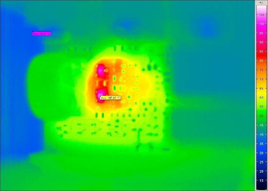
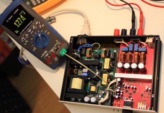
For upcoming customer subwoofer project I’m evaluating the TI SMPS Reference Design. For the first measurements I just used the original SMPS board from TAS5630 TI mass market amplifier demonstrator. I found some thermal issues on the board. All measurements were done in 21deg Celsius room temperature without enclosure, so with quite good ventilation:
- In main switcher gate control circuit, the transistors Q4 and Q5 have temperature significantly over 100 deg Celsius. The max value I measured with IR camera was over 108 deg Celsius! I can just figure how hot they will be having the amplifier enclosure closed running with 75% power for some time and having probably around 45-50 deg C in the enclosure … will the Q4 and Q5 run out of the spec or they will by right on the limit? Unfortunately I had the amp just for very short time, performing some basic electrical measurements, and had to give it back to the customer who is currently doing sonic performance analyze. In a short time I should have my own SMPS board based on TI reference design and then I will perform some more tests on it.
- In Bias Supply circuit the D4 and R5 are also quite warm. The diode D5 reached nearly 75 deg C … That’s not so bad. I know, but still significantly warmer than ambient.
All measurements were done in the idle operation. The TAS5630 amplifier board was connected but no signal was applied on the input.
My question is, if this behavior is intended by the design or just the SMPS board I have, has the thermal problem? I would suggest using low saturation voltage transistors for Q4 and Q5. It would significantly decrease switching power dissipation. It wouldn’t significantly increase cost, but would definitely increase quality and robustness of the design.
I prepared for my customer a detailed analyze document summarizing the SMPS performance. I can share parts of it with you if you like to take a look into.
Best regards,
Tomasz

