This thread has been locked.

If you have a related question, please click the "Ask a related question" button in the top right corner. The newly created question will be automatically linked to this question.

Background noise in tlv320aic3104 output

Other Parts Discussed in Thread: TLV320AIC3104, TPA3140D2

I have a custom cape on a Beaglebone Black that uses a tlv320aic3104, connected to a tpa3140d2 audio power amp. I currently manually control the /shudown pins on the two ICs, and just turn them on before doing anything else. The device is used for playback of digital audio data sent from the BBB.

The system works. But I notice that when I open the output device for writing (via libao and ALSA), I immediately hear hiss, even before I send any samples to the device. After I close the libao audio device, a few seconds later Linux sends some i2c commands to the tlv320 and it's once again silent.

The perceived amplitude of this hiss does not seem to be affected by "amixer set PCM <0 - 127>" calls.

Does anyone have any idea where this noise might be coming from? Is it just thermal or other noise in the routing of audio within the tlv320? Is there some configuration or routing I might be able to change to avoid it? Did I screw up somewhere in my circuit design or layout that only manifests when linux configures the chip for operation?

Any ideas are appreciated. Thanks.

  • Hi, Rick,

    Unfortunately, we don't support the linux drivers and ALSA. However, there are some possible solutions to eliminate noise in the TLV320AIC3104 outputs.

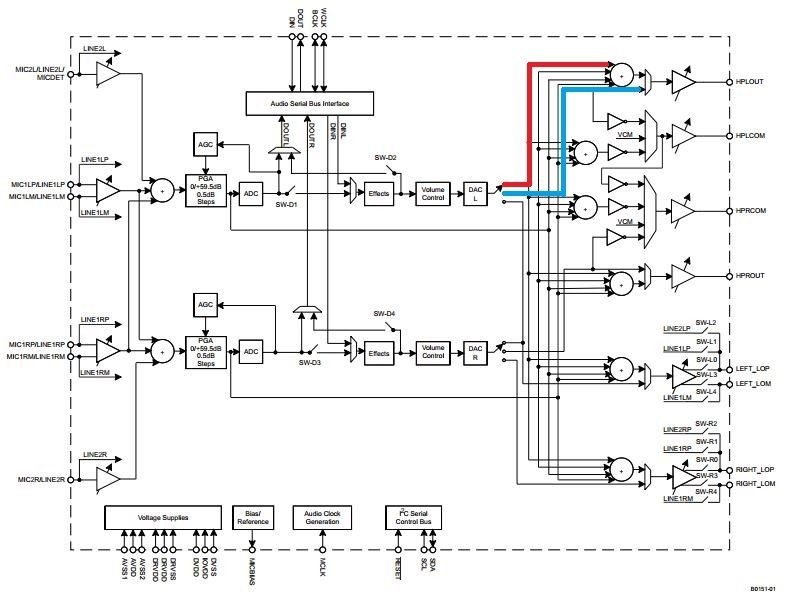
    It is recommended to use the output mixer in playback mode. I mean, the DAC can be routed directly to the outputs, but the output mixer is used as a noise filter. Please take a look of the following picture for details (red path: output mixer; blue path: DAC routed to the output).

    Then, it is important to separate the digital activity from the analog activity. Digital activity uses to affect the analog performance.

    Best regards,
    Luis Fernando Rodríguez S.

  • Thank you for the suggestion, Luis. I'm actually using the line out (differential), but I take your meaning. I'll try to figure out how to configure ALSA to set this up. I believe I did this to use the mixer bypass route, thinking that the most direct route would be the cleanest, but hopefully adding the mixer will reduce the noise. I'll let you know.

  • Actually, Luis, I'm very confused by that diagram. I want to route the DAC L output to the left line out differential output, and the DAC R output to the right line out differential output. But this doesn't actually seem to be possible. It can only be routed to the mux, and then through what I think is a PGA.

    It is, however, possible to route the left DAC to the left *and* right line out mixers. It's also possible to short the left and right DAC outputs together.

    Is the diagram in the data sheet wrong?
  • Hi, Rick,

    Both DACs have three outputs: output 1 is routed to the mixers, output 2 to high-power outputs and output 3 to line outputs. Please take a look of 10.3.6 Analog Fully Differential Line Output Drivers and 10.3.7 Analog High-Power Output Drivers sections for details.

    Actually, both DACs can be connected to the line out mixers. The following picture shows in red the path that routes the DAC_L to the mixers:

    However, the datasheet seems to have a mistake in the diagram. DAC_R can be routed to both mixers as well. The correct diagram should be as the following picture (blue path):

    Thank you for the observation and I apologize for the confusion. I will notify this mistake.

    Best regards,
    Luis Fernando Rodríguez S.

  • Hi Luis,

    Indeed, the paths after DAC_R1 are broken. They should be made symmetrical to those after DAC_L1.

    10.3.6 recommends to bypass the line out mixers (using DAC_L3 and DAC_R3) for the use case discussed in this thread in order to get higher-quality output performance and lower-power operation (same in 10.3.7 with DAC_L2 and DAC_R2 for HP out), which seems to contradict the advice that you gave in your first reply. Can you clarify this? Is there any noticeable difference to be expected?

    Also, the diagram does not show the "external feedback" setting of the HPRCOM mux (see register 38). The data sheet does not even explain what it means exactly (or I did not find it). Can you clarify this?

    Best regards,
    Benoît
  • The documentation in 10.6.1 refers to several volume controls used throughout the output stage. It would be helpful if those were called out on the main block diagram, as well. Thank you.

  • Hi,

    The datasheet has a mistake on these sections. The highest-quality output performance is reached using the line out / HP mixers. It is a trade-off between quality and power consumption. When these mixers are bypassed, there's less power consumption. Then, register 38 is related with the HPRCOM functionality, this external feedback is used when the HPLCOM and HPRCOM are connected together. An example of this configuration can be seen in "Figure 29. Configuration of Device for Jack Detection Using a Pseudo-Differential (Capless) Headphone Output Connection" and "Figure 39. Typical Connections for Capless Headphone and External Speaker Amplifier".

    We really appreciate your comments. I will notify this to avoid any future misunderstanding. Please let me know if you still have questions or comments.

    Best regards,
    Luis Fernando Rodríguez S.