Other Parts Discussed in Thread: TLV320AIC3254
Hey
I am moving cautiously this time with the AIC3254 development.
Starting from scratch, building a breakout board for the IC to test it properly. First, please review these files regarding the correct design of the breakout board, specifically the solder mask tolerance
Gerber files and PDF images - https://drive.google.com/open?id=0B3tW8HqE_ubMNTZiTlNBamhBRTJTeTlQcE41MVFyNWllT2Uw
Eagle Schem File - https://drive.google.com/open?id=0B3tW8HqE_ubMWnEtcERCbkZ4UlJSc3Y2QW1pREs1dmVBQkhF
Eagle Board File - https://drive.google.com/open?id=0B3tW8HqE_ubMeWVCRm5NRzlhOFdFQzJFeUpYV2VFamVpR25V
Since SMD components cant be used, are there anything to note while breadboarding the components, like the tolerance of the through-hole resistor/capacitors, power source, etc
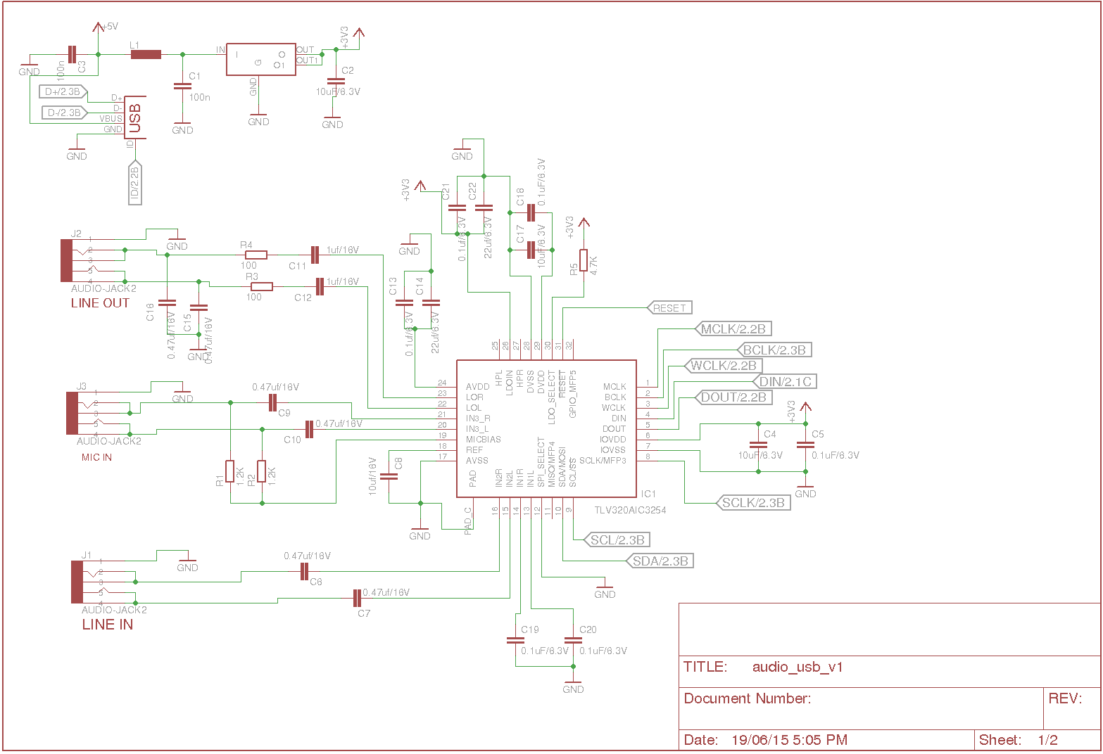
Also, attaching the codec schematic to be interfaced with an Arduino Uno.
Thanks.
PS - Maybe a little late to consult you but I should tell you that the board has already been fabricated and now waiting it to be assembled.