This thread has been locked.

If you have a related question, please click the "Ask a related question" button in the top right corner. The newly created question will be automatically linked to this question.

Class-D Amplifier TPA3116D2 driving 100V audio transformer

Other Parts Discussed in Thread: TPA3116D2, TPA3123D2, TPA3112D1

Hi,

I have to use TPA3116D2 with a 100V audio transformer, in a costant voltage speaker system(en.wikipedia.org/.../Constant-voltage_speaker_system).

To drive the transformer, I have to add an RC circuit for DC attenuation to avoid the TPA3116D2 short circuit protection near max power usage.

This RC circuit is problematic because it is a high power RC circuits(large component), and filter the amplifier input signal not solve(for THD reason i think).

There's another solution for this class D amplifier?

Regards,

Alberto

  • Hi Alberto,

    My colleague will take a look to your questions and get back to you early next Week. Meanwhile, I would recommend you to take a look to this document. Also, can you please provide more information about your power requirements and end-system?, this way we can have a better approach on how to help you. 

    Best Regards,

      -Diego Meléndez López
       Audio Applications Engineer

  • Hi Diego,
    thank you for the documentation.
    As I read, there are three strategies to avoid SCP with this setup. The third one refer to the transformer design, but I don't understand how to proceed with the first and the second one(I don't understand the statement "The existing program...": do it refer to the program inside TPA3123D2?).
    For my power requirements, I use TPA3116d2 in PBTL mode to provide 40W on 4 Ohm load (to avoid large heatsink), I don't have other data for the 100V toroidal transformer.
    Regards,
    Alberto
  • Hi, Alberto
    "To drive the transformer, I have to add an RC circuit for DC attenuation to avoid the TPA3116D2 short circuit protection near max power usage." What is the RC filter's cutoff frequency and you need a very large component? I need to check whether TPA3116's DC protection or Over current protect limit your application.
  • Hi, Alberto
    Can you provide your schematic?
  • Hi Peter,

    I don't have a law for the RC filter's cutoff, I'm doing some test here in my lab.

    Someone use this filter as a rule for the 8 Ohm case:

     For the TPA3116D2 I use the reference design in fig. 37 at page 26 in the datasheet (U2). For the inductor I use one dual inductor from coilcraft(www.coilcraft.com/.../ha4158.pdf).

    Regards,

    Alberto

  • Hi, Alberto

    So what you mean is like below?

    So what is your big concern? I am sorry I am not very familiar with your application case (end system), but I will try to understand it as a circuit module.

  • Hi Peter,
    your scheme is ok.
    Without R1 C1 C2 the shutdown is triggered by short circuit protection when you are near max power usage.
    I made some test with R1 C1 C2 and it seem to solve the problem.
    I'm trying to understand if there's a way to avoid the use of R1 C1 C2(I have space constrains and the components R1 C1 C2 are very large).
    Reading sloa133 I have some difficulties to undestand when it describe the first and second cure for the problem.
    Also please let me know if these cure are applicable for TPA3116D2 or not.
    Regards,
    Alberto
  • Hi, Alberto
    So your requirement is very clear now, we will try to find a solution for you and will update to you if we found a effective method.
  • I wonder if the overcurrent shutdown may be due to core saturation if you are trying for a lot of power at low frequency?

    100V transformer amps generally have a serious high pass on the input (and limiting the low frequency energy may be a good idea, most 100V line transformers will saturate of you try for maximum rated voltage at 50Hz or so, the iron is usually just not up to the job (And even if it is in the amplifier, it seldom is in the speakers you have connected). 

    If the issue is actually just DC offset, then a DC servo around the power amp may be a better fix then the series cap (That 50W resistor is overkill unless you are doing something really weird, is it intended to kill the series resonance or something?).

    What is the expected frequency response (And what order is the HPF), what is the transformer primary inductance and what is the transformer voltage-time product limit for the core saturation, and what is the supply voltage in your application? 

    Are you sure you have enough phase margin when the core starts to approach saturation, closed loop voltage mode controllers (Which is what this is) into a complex load can be all sorts of 'fun'. Also on that note, you do have clamp diodes between the amp outputs and the rails? The load Z can vary widely and can push current back into the outputs, clamps are a good idea.  

    73 Dan.

  • Hi Dan,

    thank you for your advice.

    I agree with you that limiting the low frequency energy may be a good idea. Also 50W resistor is overkill.

    For my use, I have at most 80-18000Hz of bandwidth. I don't have other data for the transformer.

    I have to do some test to understand the shutdown protection.

    Regards,

    Alberto

  • Hello All-
    I am following this thread as I too have to come up with a design although mine is based on the TPA3112D1 amp. However, I also need to provide a constant voltage output but 25 volts instead of 100 volts.
    The design is to replace a 30 watt intercom amp so the 25 volt setup is mandatory.
    Would an additional choke or just a simple LC filter work to eliminate the unwanted frequencies and also any problems with a transformer on the output?
    Reghards,
    Steve
  • Forgot to mention, my bandwidth is 500-1200 - basically speech.
  • 500-1200 is very narrow for intelligible speech, 300-3000 is more like it in general (and I would recommend a couple of opamps be used as a pair of second order MFB filters before the power stage).

    If you picked a slightly higher voltage part (You need ~36V rail to get 25V RMS) you could do away the transformer and run with just a butch low voltage electrolytic or two as a DC block (Or servo the DC away).

    The problem you will have is that in a constant voltage system the load impedance can vary widely which makes the output filter somewhat tricky, so you probably need to design for a range of load impedances.

    Regards, Dan.
  • Thanks Dan-
    I had planned on starting with an 8-pole filter (I am more of a digital designer) and after testing drop to 4?
    I will go with your suggestion of 300-3K for the width to start.
    I would like to experiment with a transformer-less design but I only have +24 volts available for the design.
    So, to continue, Input --> speech filer --> power amp --> back to back electrolytics --> transformer
    Am I reading you correctly?
    In this post, there is a design for back to back electrolytic at a 4700uF value. That seems pretty large. Do I really need them to be that large?
    What voltage do you suggest? 50v or 100v for some headroom?
    Sorry, but I don't do audio that much........
    Thanks for the suggestions!
    Regards,
    Steve
  • To some extent there is no need to limit the top end that severely, it is the low frequency end that saturates transformer cores, roll the top end off at maybe 6 or 8K if using a single speaker, it will sound much better then sticking to telephone bandwidth.

    The caps should not have much signal voltage across them, so you only really need a few volt rated parts here, maybe use say 16V parts with a back to back pair of 10V zenners across them to ensure faults trip the over current detect.

    As to cap value, calculate the reflected impedance on the primary side of the transformer, and have the caps form a pole with that impedance at least an octave below your HPF cutoff. Double check to make sure that the transformer magnetising inductance does not do anything unfortunate in your passband in terms of resonance with that cap.

    All that said, I would rethink a little, a boost converter to get you ~40V on the bus caps and transformerless output is going to be cheaper then an audio bandwidth transformer (One high frequency inductor Vs a relatively heavy low frequency transformer, no contest).

    Regards, Dan.
  • Thanks again Dan.
    I would to learn a bit more about this. Yes, the chunk of iron on the output (30 watts at 25v) is a bit pricey......
    But I would like to start there so I can get a grasp on this while thing.
    Thanks for the tip on the low end. I can raise the high end per your input. I am striving for a level of quality and intelligible sppech.
    I will re-figure the top end and have the band pass at 300-7k.
    I still have to figure out the best way for a limiter. I tried a THAT part, expensive and was difficult for me to understand to get it to work right.
    Then I tried a SA572 which ended up being problematic as well.
    I think instead of a compander, all I need is a limiter. Most of the time people are going to be 10-15 feet away from the speaker so I think all I need to account for is the guy who gets 1 foot away!?
    Do you have any practical experience with these?
    As far as a single speaker, yes, that would be the normal, but the 30 watt hope is that I could also use it to provide a one-way page to 20-25 speakers if they are tapped at 1/2 watt which should be well in the range of the TPA3112D1.
    Regarding the cap value, where could I go find the equation? or, is there a spreadsheet or something? The transformer could be either 4 ohm or 8 ohm input.

    Once I get my feet wet with this and it seems to work and be reliable. I will try to spread my wings and try the transformer-less design.
    I agree with you that the iron-less design should be better, but I have no comparison.
    Once the transformer design works, I can compare it against it. That make sense for an audio neophyte? <grin>.

    Regards and Thanks again.
    Steve
  • Ahhh, now I get it (with help from the net), if the turns ratio is 20 and there is 1.5k on the secondary, the primary will see 30k on the primary.
    Been so long since I think I learned that.....
    I am checking with mfgr on turns ration I would like to start with.
    Now looking into the issue of poles.....
  • Nope, mis-stated that. Forgot the square in the equation;
    turns ratio of 1:20=400 to 1 impedance ratio!
    so, a .62 watt speaker transformer at 26 ohms on the secondary gives me 10.4k on the primary.
    I need to remember all this stuff......
    Still waiting on the turns ratio from the manufacturer.....
  • I think you are over thinking it. 

    If your transformer is a 8 Ohm input then actually you can view this as an 8 Ohm design, hence primary Vrms = 15.5V for 30W, and the turns ratio is in the 2:1 region.

    Now that is only an 8 ohm load when the secondary is loaded with the transformers rated total load, 30W in this case. If you load the secondary with say 3W of speakers then you get an 80 ohm presented to the amp instead of 8 ohms (Which makes the output filter design 'interesting'.

    The transformer manufacturer will have calculated the thing such that the primary side will be the rated impedance when the secondary is loaded for the rated power @ either 25/70 or 100V depending on the iron.

    Compression or limiting will NOT help with variable distances between the listener and the speaker (it does however help with differences in volume at the microphone). 

    A simple jfet based limiter is good enough here, couple of opamps, some diodes, a cap or two and a jfet, sum half Vds into the gate voltage to reduce the distortion.

    Regards, Dan. 

  • So there is no simplistic way of adding caps.  The transformer manufacturer suggested 100uF caps back to back (non-polar)????

    I never stopped to even realize that as you add speakers with 25 volt transformers, your impedance on the primary of the D amp may change.  That being said, my 90% use id 1 other speaker/transformer.  10% of the time it may be 5,10,15, or 20 speaker/transformers.

    How the heck do you design for that?

    As far as the limiter, funny you mention the jfet approach - out of all the various teachings and schematics I have found, that was the design I wanted to start with.  Funny.

  • The caps are just there to remove any DC offset, so just design them to highpass @  a few hundred Hz into 8 ohms, it will be fine. 

    You design for the impedance change my making the filter go over above your desired operating band and making it slightly over damped into 8 ohms, and slightly under damped into your smaller load, then use the opamp filters on the input of the amp to limit the audio to a band that stops before the under damped output filter becomes too problematic (Spice is your friend here). 

    Dave Hill published a decent fet limiter as I recall. 

    Regards, Dan.

  • Thanks Dan.

    The caps confirm what I was thinking.  Remember that from my old speaker days - a LONG time ago.

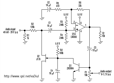
    The AGC circuit I found is this one above but I will search for that under the name given.

    As far as this pesky impedance filter, I don't have nor never used SPICE so I will be doing it the hard way by no doubt trial and error but hopefully get close before the trial and error.  I must also confess that as a digital guy, whatever I THOUGHT I learned about impedance was deleted for other stuff a long time ago.  I do remembering that it was much like RF - designed by off-world aliens.......  It just didn't make much sense to me.  Probably why I stay in digital and microcode <grin>.

    I will look into this as this may finally give me the insight I need to 'get' impedance........  Any direction on where to start the design on the impedance filter - and even what they may look like would be appreciated.

    Regards, and I do appreciate the help.

    -Steve