This thread has been locked.

If you have a related question, please click the "Ask a related question" button in the top right corner. The newly created question will be automatically linked to this question.

INT- PCM5102 charge pump switch frequency

Other Parts Discussed in Thread: PCM5102, PCM5102A

Hi Team,

I have automotive customer Desay SV that is evaluating PCM5102 for DVD I2S converter, it's for infotainment, with 500Ku/Y run rate.

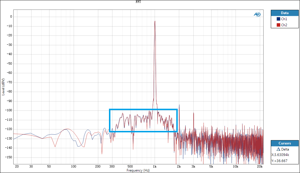
But now customer feedback meeting issue for the EMC test. See as attachment picture test results in EMC test and using frequency analyzer.

The frequency point at ~73.73MHz exceed the limit. The same frequency is detected at charge pump pin of PCM5102 using near field probe.

Could you help share with me what's the switch frequency of the charge pump ?  

I wonder if it's around 1.5MHz ? And if the harmonic would lead to the this result ?  Appreciated if you have other ideas for the possible causes and improvement methods.

I could get customer latest sch and PCB design later.

Thanks.


  • Hi Rocson,

    The charge pump frequency changes with the sampling frequency. What clocks are they running this test with? Have they tried changing the clocks to the part and seeing if this has any effect on the high frequency content they see?

    Justin
  • Hi Justin,

    Thanks for you reply.

    Customer is using sample rate of 48KHz, which is standard I2S flow from DVD decoder. So it's fixed.

    I'm asking customer to help check if being able to have try for change to compare, waiting for confirm.

    But for the real case usage, 48KHz is required.

    For the schematic and PCB design, I just got it, and seems it's ok, see as attachment.  Please help check if other comments ?

    Thanks.

    7043.PCM5102 SCH&PCB LAYOUT.xlsx

  • Also, is there any calculation formula about the sample rate and charge pump switch frequency ?
    Thanks.
  • Hi Justin,

    I did tests with customer today, try using 2 different disk with 44.1KHz and 48KHz sample rate respectively.

    Based on the scope frequency analyzer, the EMC failure frequency point do from charge pump switch. See as attachment waveform summary.

    Need you help as below:

    1. Could you help review the schematic and PCB design if any comments for improvement about this issue ?

    2. For the charge pump design, what is the working principle with sample rate ?  

    3. For this issue, any other external circuit could be added to reduce the radiation of switch frequency ? 

    Thanks for your help.

    PCM5102 test of Desay SV.docx

  • Hi Rocson,

    It looks like the grounds are separated under the PCM5102A, could you explain more why this was chosen? On the EVM we have a single ground, does  the EVM fail this same EMI test that your customer is running?

    Options to try:

    1. Connecting the ground planes near the PCM5102A. (bluewire to test)

    2. Creating one ground plane. (layout change)

    Below is the EVM layout:

    Justin

  • Hi Justin,

    Customer separated the AGND and DGND, with the purpose of avoiding the negative effect of digital I2S signal on analog output.

    So do you think just single ground plane is ok, without needing to separate digital and analog ?

    Also, do you have any EMC test report for EVM or data of other customer case, that could share with me ?

    Except for the GND layout, do you have other idea that we could try, like cap value, RC snubber(seems not practical for PCM5102A charge pump), or other circuit could be of help ?

    We are trying to get one EVM and might connect the customer DVD decoder interface to EVM for test, but I' worried it might be worse as EVM has no shielding. (customer total PCB board was in one metal box, as DVD module)

    Thanks.

  • Hi Rocson,

    I have spoken with a senior apps engineer who is focused on automotive applications for our amplifiers, and he agrees that the biggest issue we see is that the grounds are separated. This will cause return currents to either cross the part or have to travel around the board unto it can transfer from one ground to the other. It would be helpful to see all the layers and the entire board .

    Justin

  • Hi Justin,

    Thanks for your comments.

    Customer have made some modification to make the loop smaller, and also make the charge pump flying cap in ground loop. 

    But still, as Car OEM Mazda requires high quality sound effect, customer is worried if I2S digital signal would affect the analog output So that's why they want to separate the AGND and DGND. 

    Do you have other comments for this aspect of design idea ?

    Based on the current modification as attachment, could you help double check if other comments ? Also, we have suggested customer to make one single GND plane in next PCB to try compared test.

    Thanks.

    PCM5102A SCH&PCB LAYOUT- update.xlsx

  • Hi Rocson,

    If you have a single ground with sufficient partitioning of the signals so that the return paths of the digital signals do not cross the analog output traces, then they should not have a significant impact on each other. With good partitioning of the analog and digital signals, I believe that the digital signals will not effect the analog output. Is there a ground layer below the layer in the attachment?

    Justin
  • Hi Justin,

    This is a 2 layer board design because of cost.

    As you see from the attachment, they reserve one AGND ground underneath the PCM5102A on top layer(blue color), and make separate and make the single point connection between AGND and DGND right under IC on same bottom layer (brown color).

    The purpose is to make the return path as short as possible, and greatest plane for PCM5102A as large as possible, while still keeping separated to avoid digital signal effect.

    Customer is to send out this PCB version to make board tomorrow, could you help check if more other comments or component placement? (based on separated ground for this version)

    Thanks.

  • Hi Rocson,

    The latest layout you sent seems better, but my recommendation would still be to have a single ground plane with good partitioning. One question I have is what are the connections here? I think having this connection below the part will perform better than the origional layout, but I am not sure what the pink devices are.:

    Justin

  • Hi Justin,

    I posted another quote about PCM5102A, but I just remember I might should come back to this post.

    Some update about this EMI issue.

    Customer made another version PCB, and now we find that the EMI source actually is from I2S clock, rather than charge pump.

    We tried adding one L +C in series with BCLK pin, and one paralleled cap from pin to GND, it helps to reduce the EMI/RE from I2S clock. But we finding that larger value of R +C would make the immunity bad and affect the audio sound, which means some times there is no output.

    So we are thinking how to choose to correct value for RC. Could you help for that ?

    Also, 2 more question from customer:

    1. For I2S clock pins, like BCLK,  SRCK, what's he equivalent input capacitance from pin to GND internally ?

    2. For BCLK clock, what's the max jitter tolerance for internal PLL of PCM5102A to lock ? 

    Could it because the slope of clock is slow that noise is easy to couple and make the clock sampling worse, when using larger RC values ? And could the slow rising edge lead to PLL unable to lock ?

    Thanks for your help and support.

  • Hi Justin,

    Could you help with the questions above ?

    Thanks.

  • Hi Rocson,

    We don't have measurements for jitter tolerance for the PCM5102A. we also don't have optimal RC values for this situation. Could you post the new PCB layout showing the I2S traces and ground planes? I believe this is still a current return issue, in that the clock signals do not have a straight path available for current return over the ground plane. This will cause the return path to become an antenna and will cause EMI issues you are seeing.

    Justin
  • Hi Justin,

    Thanks for your reply.

    The test is based on the PCB layout updated version as we discussed right above, with separated ground but connected with single point, see as attachment as below, same with last one. Just check you might have one question I forget to feedback, the pink connection you pointed out with red circle is just copper of layout, not real SMT component.

    During the tests, we find that adding RC in series of BCLK do help for the EMI issue. (R in series and C paralleled), as some small overshoot and ringing could be observed without RC.

    But customer want to check what's the pin equivalent capacitance of BCLK, so that they could calculate and choose suitable value RC to solve this issue.

    Are you able to help check this parameter ?

    Thanks for your help.

    8371.PCM5102A SCH&PCB LAYOUT- update.xlsx

  • Hi Rocson,

    Sorry, we do not have any statistical data for the equivalent capacitance of the BCK pin.

    Justin
  • Justin,

    Then what's your comments to add RC to improve this EMI issue ?
    And how about the layout ?

    Thanks.
  • Hi Rocson,

    Its possible the RC filters could help out, but if the return path from the RC filter is just as bad it could present the same problems. Our recommendation would be to make one ground instead of a split ground.

    Justin
  • Hi Justin,

    We have tried tuned and tested with customer for this EMC issue, and now with just  resister R=470ohm in series of I2S clock and data, and remove the cap paralleled, the EMC/RE and RI is able to pass now.

    But one new question that need you help is, input with 1KHz signal, and do FFT for the PCM5102A output, finding that there is some strange spectrum. Also tried with 5-10KHz signal input , it's similar. Also, they test with same condition on NXP DAC, but no such spectrum.

    see as below picture waveform in blue box.

    Could you help comments if any possible reasons ?

    Thanks.


  • Hi Justin,

    Could you help about this topic right above ?

    Thanks for help.