This thread has been locked.

If you have a related question, please click the "Ask a related question" button in the top right corner. The newly created question will be automatically linked to this question.

Signal distortion Problem using LM1036


Dear All,

I made a Vol-Bass-Treble control circuit using LM1036. I did the following:

(1) Made PCB as per standard designs available in different websites. 

(2) Took care of Ground Loop.

(3) made a regulated +12V supply using 7812 with proper filtering.

(4) This circuit is driven by a pre-amplifier stage with 220mv output.

(5) Pre-amplifier output is 100% correct as seen in Oscilloscope.

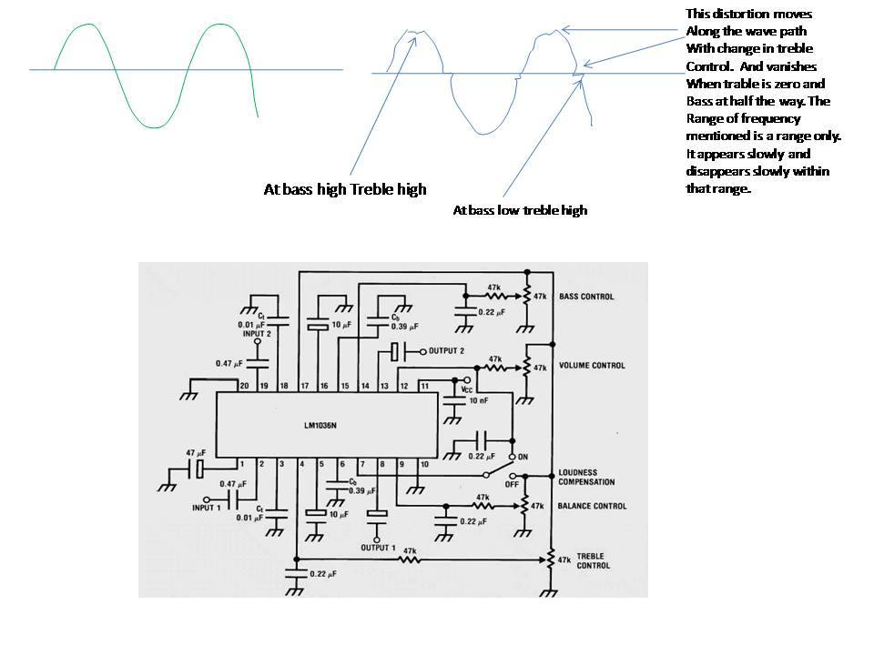
(6) LM1036 out put is perfect and working ok with cut and boost at low (40 Hz) and high frequescy (10KHz).

(7) but at 900 Hz to 3 KHz signal get distorted if Bass and Treble is increased. With Min Bass & Trable

      waveform is perfect. Though there is no cut and boost at that range.

Please suggest me the solution to avoid the problem.

regards,

Debasis Debnath

rupan_debnath@yahoo.co.in

+91 9433 887541

  • Hi Debasis,

    Welcome to e2e

    Could you share your design so we can take a look for any possible issue in there?
    Also I would like to ask you a couple questions. What kind of distortion is it? Do you have captures of the distortion? Does the distortion appears gradually as the signal comes into the 900-3000Hz region you're referring?

    Besides, unfortunately LM1036 is in Lifebuy state right now as it will be discontinued, so it is not recommended for new designs.

    Best regards,
    -Ivan Salazar
    Texas Instruments
  •  Hi Ivan,

    I am attaching the wave form and circuit as a jpg image.

    One point I forgot to mention that the Zenor Voltage level is 5.59 V as it is coming instead

    of 5.4 V as in data sheet. Distortion is something like crossover distortion which moves

    along the waveform from peak to crossover point. Its like a notch in the waveform.

    (1) When Bass & Treble both high -- Notch is at both the peaks which folds the wave.

    (2) When Bass min & Treble high ---  Distortion reduces a little and shift along the wave.

    (3) When both treble and Bass is low -- Distortion disappears. Waveform is crystal clear.

    (4) Actually at this range of frequency there is 0db gain, so there is no change in gain observed.

    Please suggest.

    Best regards,

    Debasis Debnath

  • Hi Debasis,

    You say you're using a 7812 with "proper filtering"; how much filtering and of what kind? The datasheet shows a 10nF cap on the Vcc pin; do you have anything else there as well? I'd start by hanging a 470µF cap off that pin and see where you are. 

    Also, a 100pF cap on the inputs to ground... Is this on a PCB, or are you using a white "prototype" plug board? If the latter, you will see all kinds of anomalies.  

    Mike T.

  • Hi Mike,

    It is a PCB made by me (attached). 7812 is having filters with
    o.01 uf & 1000uf capacitor. 

    I tried with capacitor 220pf/100pf at the input to Gnd. No change.
    Actually that reduces noise, nothing else. Actually the cross over
    distortion comes when the current source in-chip may not be in a 
    position to provide required current during charging and discharing
    of capacitors connected for concerned purpose. 

    best regards,

    Debasis Debnath

  • Hi Debasis,

    What is your input level? Have a look at the "Signal Handling" section of the data sheet. Are you going outside the values shown? The data sheet uses 0.3Vrms (0.8485Vp-p) for their tests. The input level is tied to the settings of the tone controls; I'd be careful not to exceed the ~1Vp-p level.

    In looking at the schematic for the device, the AC Bypass is brought out. They show a 10µF cap; I'd also put a 0.1µF ceramic cap in parallel with the one shown. I also don't see any harm in making the 10µF bigger...

    Mike T.
  • Hi Mike,

    You are 100% correct. I have seen the input level also. Device functioning
    ok at 1KHz (with bass treble min) upto input level of 1.2 V. I use 220 mv
    rms level as a standard AUX input for this. At high i/p, o/p clips -- standard
    issue. 

    What I feel is that we need to put some resistance some where in the biasing
    side to provide required current to drive the next stage. But I am confused
    when the same circuit function perfect at 40Hz and 10 KHz (absolutely with
    no issue). There is high frequency noise at the o/p at max treble max volm, but 
    that is not a big issue and can be managed as it is within limit.

    Distortion is peculiar. I am sure that the IC has no design problem, problem
    is at my end only -- but could not get it. Please suggest from your experience
    in handling such unknown -unexpected-peculiar problem.

    best regards,

    Debasis


  • It sounds to me like it's oscillating, which kind of follows from the signal diagram you drew. Did you look at the decoupling and AC bypass? I'd put a scope on the AC bypass pin and monitor that as you sweep the input frequency.

    It doesn't help you with this device, but it was pointed out that this device is EOL. A couple of opamps and a handful of discrete components and you can reproduce what this IC does...

    Mike T.

  • Let me check again as you said.Thank you sir.


  • Just out of curiosity; what is the output impedance of the device your using to test the LM1036?

    Mike T.

  • Hi Mike,

    Out put device is an Oscilloscope 20MHz Scientific. 

    Mike, the problem is resolved today at 4 pm. Sorry the problem
    was at my end -- it was two folded issues.

    (1) The out put of the signal generator had some problem. But the input
        (whatever it maybe -- sine in nature) should be reproduced at the 
        output. I fine tuned the generator -- problem reduced.It stopped at
        cross over distortion level. Top folding vanished.

    (2) Actually I used C_bass 220 nf and C_trable 20 nf. I changed the value
        of C_trable by 10 nf and distortion reduced drastically. 

    Now I may change C_Bass to 390 nf -- Thinking. As such no issue.

    But would you please tell me whether this IC can handle any signal (other
    than sine) in the prescribed range of 20 Hz-20 KHz @ max 300 mV level.

    Please give your comment.

    best regards,


    Debasis Debnath 
  • Hi Debasis,

    I'm glad you're getting closer to a final solution.

    FYI - As we know this device is EOL. I was looking at JRC's website yesterday and saw that they have a number of devices very similar to this one. There is nothing "pin-for-pin" but many with the same functions (or more). In most cases however these are not strictly "analog" devices but have a serial connection for setting some of the parameters.

    Good luck!

    Mike T.
  • Dear Mike,

    Please find attached the wave forms:

    (1) Image-001 -- Perfect wave form below 2 KHz and above 12 KHZ
    (2) Image-002, 003, 004 & Image 005 -- the waveform in between 2 KHZ to 12 KHZ

    Capacitor used are 0.39uf and 0.01 uf. 

    If I remove treble capacitor and keep the pin open wave form is ok, without 
    any boost and cut.

    For your analysis please.


    regards,

    Debasis Debnath