This thread has been locked.
If you have a related question, please click the "Ask a related question" button in the top right corner. The newly created question will be automatically linked to this question.
I'm Tsukiyama Masahiro and electrical engineer for motor driver circuit.
There is a problem with LM3886 operation at low temperature.
It does not work at low temperature. But it works at room temperature.
Would you tell me any advice what problem is or LM3886 has any damage?
Two LM 3886 ICs are used in our motor driver circuit. The circuit configuration is bridge type.
We found that our motor did not work at low temperature and it seemed that one of two LM3886 ICs did not work at low temperature.
- Usage condition
Power supply : +/- 24 V
Operating Temperature : 0 to 50 degree C
Circuit board has heat sink and cooling fan. IC mold temperature is controlled below IC's specifications.
Motor : inductance 173uH, Coil resistance : 1.07 ohms
Gain : 11
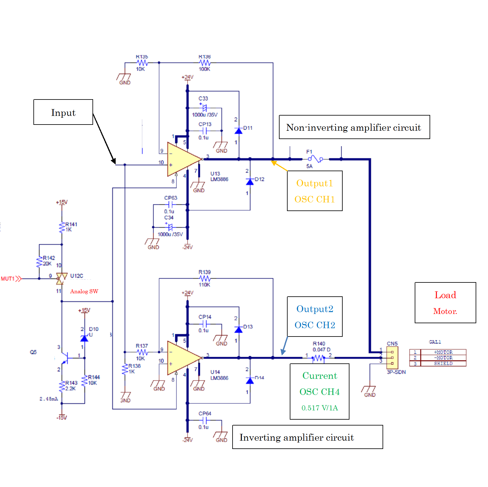
- Circuit around LM3886
The circuit to verify the root cause of abnormal operation of LM3886 is below.
The load is resistor 1k ohms instead of motor.
The input is used a function generator, it is connected to LM3668 10 (Vin+ )
Input signal : Square wave, Sine wave, 100mVp-p, 10Hz
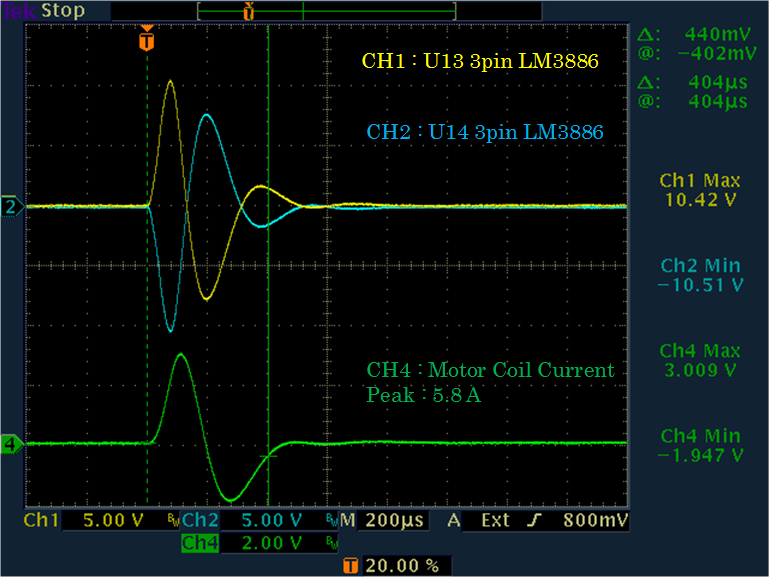
- Oscilloscope measurement
The probe definition
CH1 : High side LM3886 Output 500mV/1DIV
CH2 : Down side LM3886 Output 500mV/1DIV
CH4 : Input signal 50mV/DIV
Hello Jose,
Thank you for your quick response.
Our driver board with LM3886 ICs have been already mass-produced. There are four LM3886 ICs on our driver board.
We tried some servo tuning and the shipping inspection for this driver board at room temperature by using the trouble driver board.
Then we found that we could do them and the test was PASS.
That is very critical issue for us, because we CAN NOT inspect correctly, if LM3886 is damaged and there are any problems.
Please let us know any solutions, root cause, or advice soon.
And would you like to analyze that defect together?
Waveform measurement of LM3886 output pins (When motor is connected to driver board)
In previous schematic, load is resistor 1k ohms, but true load is motor's coil.
It seems that U14 LM3886 works well.
The defect IC (maybe) still remains on the our driver board.
U13 LM3886 mold temperature, U14 LM3886 mold temperature and room temperature
Schematic
Hello
1.Temperature range where this condition happens
The procedure that this condition happens
1. The driver board with LM3886 is left in thermostatic chamber at 0 degree C for about 1 hour. (No applied voltage )
2. Applied voltage +/-24V
3. After applied voltage +/-24V, input signal.
4. High side LM3886 (U13 Non-inverting amplifier circuit) works normally [reference previous schematic ]
5. Down side LM3886 (U14 Inverting amplifier circuit) does NOT work [reference previous waveform]
6. This defect happens under condition of repetitive voltage +/-24V is applied.
7. Voltage +/-24V and input signal are applied at 0 degree C continuously.
8. Change chamber temperature at 25 degree C (IC's mold temperature is not monitored)
9. After a period of time, Down side LM3886 (U14 Inverting amplifier circuit) starts working normally. [reference previous waveform]
I think it seems that this defect has hysteresis operation thermally.
2. Does this condition happen in all the boards?
No. Only this one. The marking on IC mold is following
Down side LM3886TF 4BAX4YUE3
High side LM3886TF 4BCC49UE3
In my opinion, We'd like your team to research whether this LM3886 can pass your shipping inspection checker test or not.
We are fairly worried about an outflow of this defect to our customers.
Best regards,
Thanks
Masahiro Tsukiyama
Hi Mike
Thank you for your advice.
I'll try do your test tomorrow. I'm sorry but I don't know understand well and have poor knowledge of internal circuit for OP.
So would you give us more detail information and advice? We have some questions.
Question 1
Attach two diodes in anti-parallel across the input pins (9&10) of U14
They mean the location of diodes in figure below, right?
Question 2
How is applied signal condition in input?
How is the temperature, at room temperature or low one?
Question 3
When input signal is applied with two diodes in anti-parallel, what is the difference between OK driver board and NG one at output?
We'll do test both OK board and NG one.
Question 4
Can we know if abnormal operation LM3886 is broken by that test?
If broken, what is the test result?
if not broken, what is the test result?
We'd like to find any solutions quickly. because we have to do shipping inspection test under low temperature.
We'd like to know if this LM3886 (U14) is broken immediately. Is it possible to check easy test of LM3886 in your company in Japan?
Best regards,
Masahiro T.
Hi Masahiro,
The data sheet shows an "equivalent schematic" (excluding active protection, so it says). Up until relatively recent times, phase reversal was a common issue with op amps. You're facing a whole slew of issues regarding VBE vs. Ic; obviously I can't speak for the designers of the device, however, given this device is designed for driving a speaker in an audio application, I don't think they considered what happens with the device at 0℃.
The diode idea is a band-aid, something to "try" and see if it helps. We can't do anything to the device internally, so all we can hope for is to find "something" that prevents this condition.
It doesn't help you with boards ready to ship, but why use analog amps when devices such as the DRV8701 exist? http://www.ti.com/lit/ds/symlink/drv8701.pdf
Mike T.
Hi Mike,
We have been using LM3886 as " B class " amplifier for servo motor driver since a few years ago.
And we are still manufacturing driver boards. That features are matched in quality of servo motor.
Almost driver boards have two " B class " amplifier bridges, so four LM3886 are used.
That is our answer.
By the way, we did the test that you advised yesterday. As a conclusion of that test, we can not find out any solutions unfortunately.
Test condition is below
- Temperature: Start 0 , 10, 20, 25, 30, 40 and 50 degree C (Temperature in thermostatic chamber ) measure after each 30 min.
- Test board: two " B class " amplifier bridges.
One is the high side U13 and low side U14, The other is high side U15 and low side U16
- Attached diodes in anti-parallel across the input pins (9&10) of low side U14 and low side U16, (Diode is DAN217)
w/ diodes and w/o diodes
- Input voltage
Wave form: Sine wave, Square wave
Amplitude: 100mVp-p, 200mVp-p, 500mVp-p
Frequency: 10Hz
- Output load: 1k ohms
Test result
- The phase-reversal of U14 is seen between 0 and 20 degree C.
- There is no difference between w/ diodes and w/o ones attached input of U14.
- The phase-reversal is unrelated to the amplitude of input voltage and form (Sine wave and Square wave).
- U14 changes from phase-reversal to normal operation approximately between 20 and 25 dgree C
Detail is below
OK: Low side OP normal operation
NG: Low side OP phase-reversal
The result, we guess that U14 LM3886 has any problems. If our test condition is not good, please let us know about that.
Although we are using a lot of LM3886 ICs, It is the first time that this symptom occurs at our customer.
We'd like to know if that LM3886 IC is broken asap. I would be grateful for your support to solve this problem.
Best regards,
Masahiro T.
Hi Mike
We tried removing U14 OP and U13 OP from PCB and changing U14 LM3886 OP for U13.
U14 OP is used in non-inverting mode. (Inverting mode in the original circuit)
U13 OP is used in inverting mode. (Non-inverting mode in the original circuit)
The result in non-inverting mode was also as same as inverting one.
Test procedure
1. Remove U14 OP and U13 OP.
S/N : U14 LM3886TF 4BAX4YUE3
S/N : U13 LM3886TF 4BCC49UE3
2. Operating check of OPs to see if there was a change in electrical characteristics by the thermal when OPs were removed.
How to check : Removed OP lead pins were connected to PCB by lead wires. And input signal, then measured output signals.
U14 LM3886TF 4BAX4YUE3
U13 LM3886TF 4BCC49UE3
3. Changing U13 for U14. And input signal, then measured output signals with changing temperature and input signals.
U14 OP is used in non-inverting mode.
U13 OP is used in inverting mode.
Test result
2. No change in electrical characteristics
U14 changes from phase-reversal to normal operation approximately between 20 and 25 dgree C
Test condition is below.
- input signal form : Sine wave, Square wave
- input voltage amplitude : 100mVpp, 10Hz
3. Non-inverting mode was also as same as inverting one.
- The phase-reversal of U14 is seen between 0 and 20 degree C.
- The phase-reversal is unrelated to the amplitude of input voltage and form (Sine wave and Square wave).
- U14 changes from phase-reversal to normal operation approximately between 20 and 25 dgree C
Detail is below
OK: Normal operation
NG: Phase-reversal For reference
The phase-reversal was also seen in non inverting mode, and the phase-reversal occurs in the same thermal condition both non inverting and inverting mode.
We are thinking that LM3886 IC is broken.We have high hopes of TI's help for that defect analysis.
Best regards,
Masahiro T.
Hi Masahiro,
It looks to me like you have identified a problem with these devices. If it were me, I would make a small PCB with an op amp and the LM3886 on the same board. I would design it such that you can remove the LM3886 from the board and replace it with the new small board with the inverter. There are op amps in SOT-23 packages; this "fix" could be very small to satisfy current production, and changed on the main PCB for the future.
Mike T.