This thread has been locked.

If you have a related question, please click the "Ask a related question" button in the top right corner. The newly created question will be automatically linked to this question.

PCM9211EVM - Dead on arrival

Other Parts Discussed in Thread: PCM9211

Hi,

Have just purcahsed at PCM9211EVM but it appears to be dead on arrival.

Carefully followed instructions in user manual.

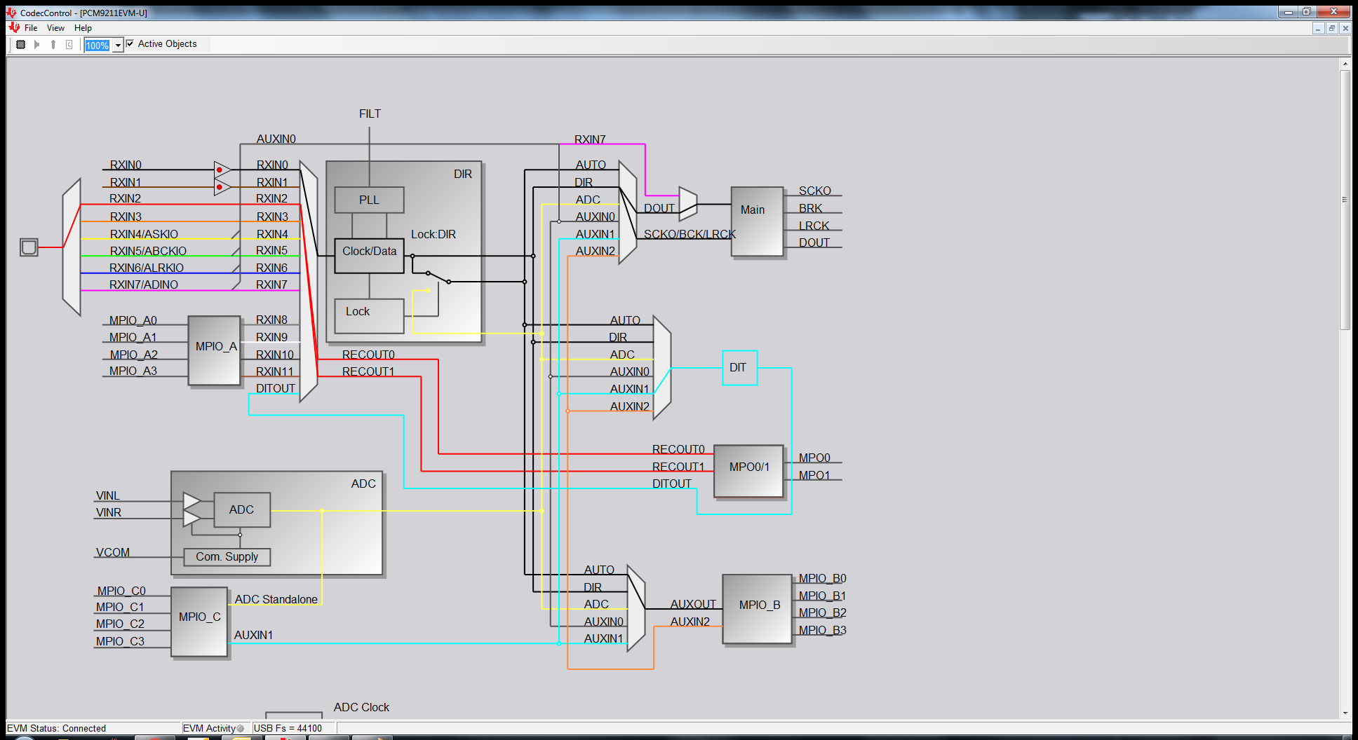
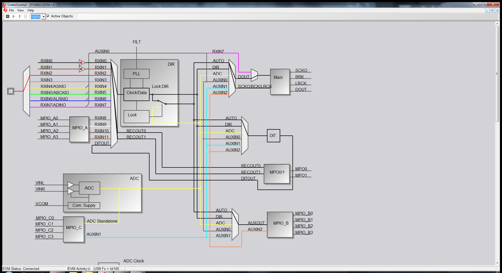
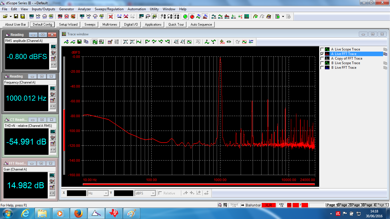
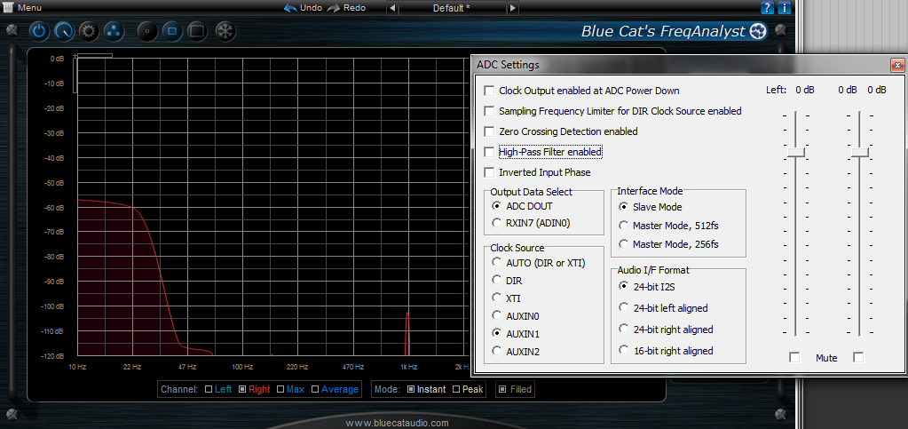
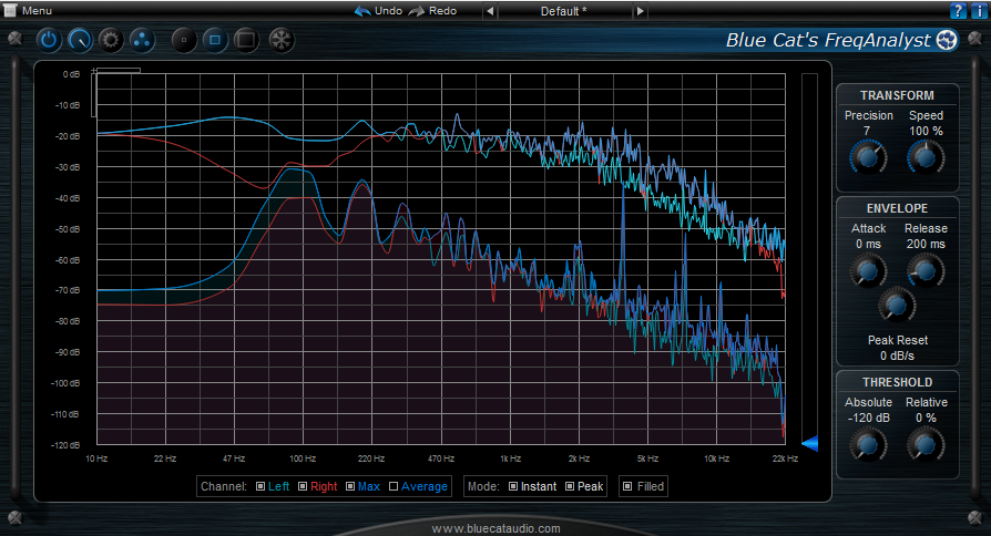
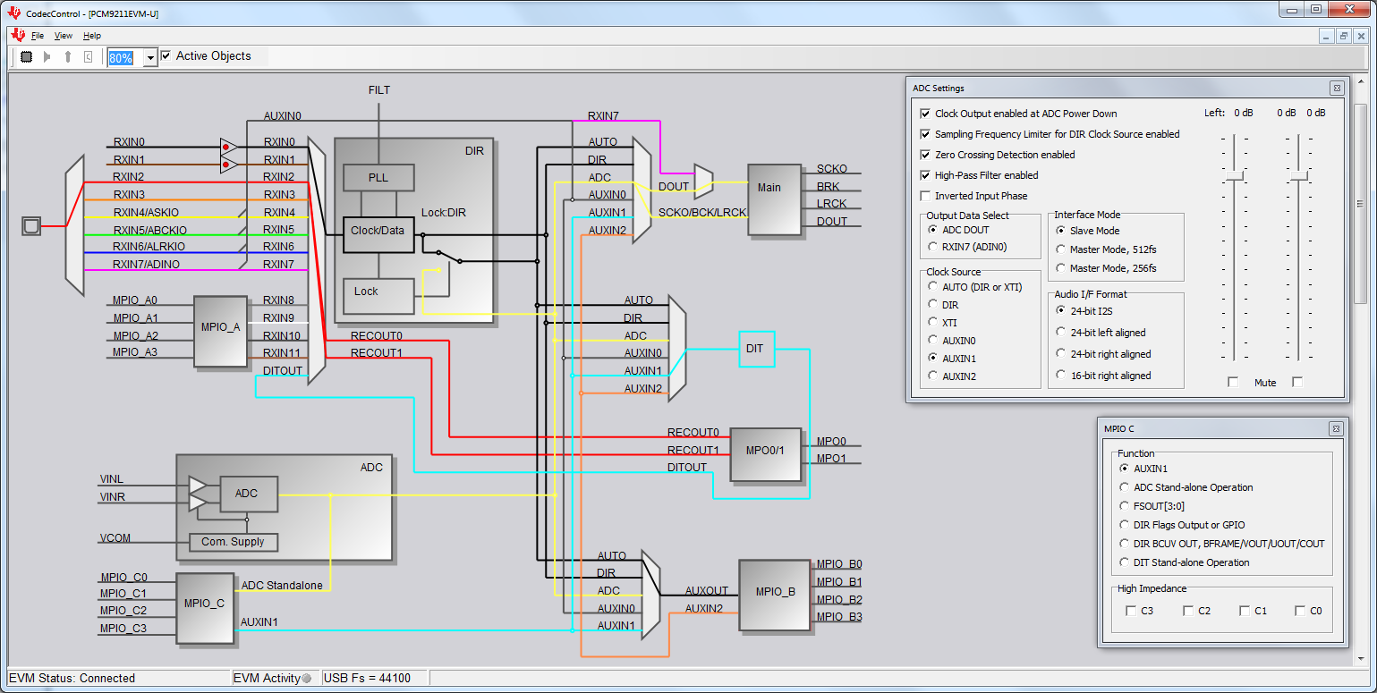
Drivers look to be installed OK and CodecControl recogines the board correctly, but the D4 error LED is constantly lit and there is either just noise or a very distorted output (changes randomly each time I press the reset button). This is whether I use the TAS1020 for USB audio or connect the Optical output to my audio analyser.

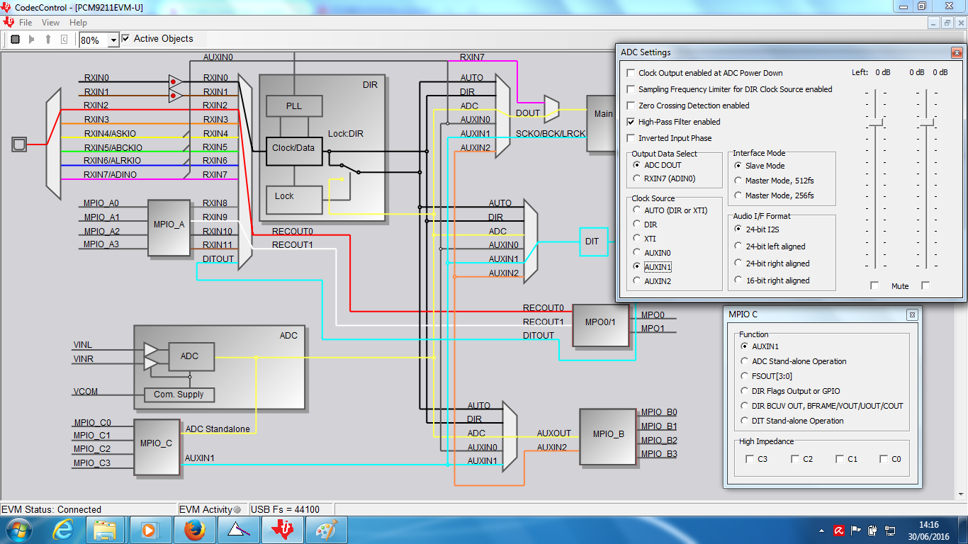
I have tried many things such as reinstalling drivers, changing PC, uploading different applications, reset board, etc. SW2 and SW3 also appear to not be doing anything.

Please could someone from TI suggest a way forward.

Thanks

Elliott

  • Hi Elliot,

    What does your system look like, what are you inputting and on what port, and what are you outputting and on what port? Could you post the script you are using for the EVM, or identify the script from the software you are trying to use?

    Justin
  • Hi Justin,

    The system is just as described in the manual - SPDIF input from my sig gen to PC output via USB. As this didn't work I have also tried all the other I/O combinations and none of them are working.

    Regarding scripts again it was just running the standard initialisation script described in part 1.3 of the manual. I also tried a variety of the scripts that come with the installation of CodecControl but none of them are functioning properly.

    Thanks

    Elliott

  • Hi Justin,

    I have been looking again at it today. With the standard startup script I still have no audio from the USB device, just full scale noise.  Settings shown below:

    I have found that if I use the following settings I can get good audio from the optical output, but still just full scale noise on the USB audio:

    If I switch the RECOUT0 and RECOUT1 source to be DITOUT on the input MUX I do not get any audio, and also if I click on MPO0/1 and set them to TXOUT there is nothing.

    I have also tried using the ADC input as shown below:

    In this case my audio analyser cannot lock to the optical output if MPO0/1 are set to RECOUT0/1. If I set them to TXOUT the analyser can lock but has no audio.

    The soundcard output is variable, sometimes it is full scale noise, sometimes it is -100dBFs, but at no point is it correct audio.

    I have also tried more of the commands cripts that come with the install but none have been successful.

    One question I have (other than the obvious'why isn't it working?') is regarding the switch underneath where it says 'Lock: DIR' in the DIR box - this never seems to change. In what situation would you expect it to switch over to the ADC position? Is this automatic or something that is set in the registers?

    Thanks

    Elliott

  • Hi Elliot,

    I will want to set this up in the lab myself to make sure I test the things I am suggestion, so I will get back to you after I have been able to spend some time in the lab on this.

    Justin
  • Hi Justin,

    Have you had any progress on this? I tried following the guide in SBAA179 but still no luck getting it to function properly.

    I think this afternoon I will have to manually check through all the registers, but it would be good if you can provide any further guidance.

    Thanks
    Elliott
  • Hi Elliot,

    I can get inputs and outputs from optical to main output, and SPDIF to main output, with correct audio. I can't however get the USB record to work correctly. I am continuing to work on this. Using the SPDIF record through RXIN02, I am getting good I2S output on the main output port, but the usb data I am getting back is incorrect. This might be a firmware issue for the TAS1020B. I know you stated that you updated the firmware, what version are you using?

    Justin
  • I, too, appear to be having similar lack of success with this evaluation board, purchased last week. Following the route suggested in "PCM9211EVM Record and Playback via USB Interface" by Tahar Allag, SBAA179-November 2010 results in an extremely low audio in signal (thru the stereo jack) amongst an awful lot of noise.

    A two year old thread twixt one jay steele and expert D Hartl - (e2e.ti.com/.../1165564
    pretty much describes my situation, so I'll just point there for further detail. The thread ends, abruptly, with an instruction to remove jumper W9. Nothing further. (My removal of said jumper appeared to have no effect).
  • Hi Justin & Paul,

    Sorry, I haven't had any time to look at this again yet, but the problem still persists.

    In reply to Justin: I don't think I have updated the firmware, there is no updated firmware available on the PCM9211EVM web page that I can see. According to CodecControl the firmware is version 2.04.

    To address Paul's points: Yes I also found that thread and tried with W9 removed - seemed to have no effect 

    Thanks

    Elliott

  • Hello,

    I also experienced the problems mentioned in this topic.

    After a lot of troubleshooting, reading the PCM9211 datasheet and the SBAA179 document over and over again, I tried the suggestion in the other topic: remove jumper W9.

    Initially, it doesn't seem to help (for some reason I can't figure out yet), but after pushing the reset button on the EVM, everything started working without problems!

    Checking the schematics again, the jumper on W9 pulls both output enable pins of U7 low, thus enabling the gates between 1A-1Y and 2A-2Y, which causes WCLK and BCLK of port C (to which the TAS1020 is connected) to get 'hard-wired' to the WCLK and BCLK of the Main Output Port of the PCM9211.

    This causes disastrous interference of the clock signals the TAS1020 sends to port C to drive the ADC in the PCM9211.

    Removing the jumper on W9 causes R24 to do its job: pull the Output Enable pins of U7 high, thus disabling the connection of the WCLK and BCLK signals between port C and the Main Output Port of the PCM9211.

    For some reason, a reset is necessary to get the PCM9211 (or the TAS1020) used to the new situation.

    So in short: remove jumper W9, push the reset button and configure the EVM according to SBAA179.

    Hopefully, you guys will now be succesful ,too!  :-)

  • Hi Marco,

    Thanks for your reply. I have had a quick look at it again this afternoon based on your recommendations.

    Removing W9 and then resetting did not immediately produce good audio, but I have found that if I change the ADC clock source setting away from and then back to AUX 1 gives some audio. I suppose that the it needs resending after the reset, it is strange that this is not needed for any other setting.

    Although this produces some audio it has a very high THD, around -54dB, so clearly something is still not right. Photos attached for reference

    Justin do you have any further suggestions? It has been almost a month now and I still do not have the board working as it should.

    Thanks

    Elliott

  • Yup. After removal of W9 and a reset I was still getting masses of signal burying noise on L & R channels with the SBAA179 instructs. But - as Mr Whyte suggests - switching away from and then back to AUXIN1 appears to clear it. If you hit reset again, the noise comes back, but flipping from AUXIN1 to (say) AUXIN0 and then back to AUXIN1 again clears the noise. It's completely repeatable.

    I also see a difference on a 1k 0.5V Sine signal, with the enabled and disabled Hi-Pass filter ADC Settings checkbox (again, a la Mr W's image above) - no filter:

    Then with filter:

    But the low frequencies may of course be coming from elsewhere - I'd not blame the card.

    Finally, here's a Harrison Birtwhistle String Quartet, with peak L & R spectros.

    So, still a bit of principle-of-least-astonishment-violation weirdness with the state machine, but it seems it _is_ possible to get something in through the stereo jack.

  • (I should add that - contrary to any indications that plonking the ADC window right on top of the spectrogram may suggest - I'm not trying to hide anything horrible. There really was nothing at all to the right of the 1kHz spike).
  • Hi Paul,

    Good to hear that you have confirmed my experiences.

    I must say that looking at your FFT the peak at 1kHz seems very low for a 0.5V input signal. Less than -100dBFs, in the same order as the DC offset/very low frequencies, it does not look correct. On the other hand you clearly have some audio in your last screenshot. Do you have a figure for THD+N?

    I will have to look in to why my board has such poor distortion performance.

    Thanks

    Elliott

  • Well, these are the steps I made to get the EVM working:

    - Remove jumper W9

    - Connect the EVM to USB

    - Connect an audio source to the analog input of the EVM

    - Start CodecControl (during start-up, CodecControl will detect and initialize the EVM)

    - In the GUI, connect DOUT to the main output block to ADC source

    - connect the SCKO/BCK/LRCK also to ADC source

    - In the MPIO C configuration, set the function to AUXIN1 (default)

    - In the ADC Settings, set Clock Source to AUXIN1

    With these settings, I get flawless audio channeling through the EVM.

  • I'd not noticed its value so you might be right there! A spike at 1kHz, no matter how tiny, just satisfied my confirmation bias. I'm looking at the signal generator again as it seems a bit flakey. With no 'input' at all I do indeed see something rather more akin to your FFT - which seems slightly alarmingly noisy but of course the decibel level is pretty low and more or less inaudible.
  • That sounds like a plan. Do you know how to do that in script? Watching the status line as I do things in the (intuitive?!) UI, I've managed to reliably perform only one of the actions, i.e. w 80 60 24, which (writing to I2C device 128, register 96, value 36) makes the (cyan line) connection from AUXIN1 to DIT. But as for the rest I can't work out what to do. For the life of me I can't see anything in the documentation (either SBAA179 or SBAA495a) which explains how to script. Am I missing something because the latter document is so large?
  • I can't get the hang of writing to register 107 (6b) correctly but this script seems to go most of the way, if run after a reset. It includes the ADC settings switch, register 66 (which seems to need a set from somewhere other than AUXIN1 to AUXIN1)

    w 80 34 c2 02 09
    w 80 34 c0 02 09
    w 80 34 00
    
    w 80 6b 24 00
    
    w 80 60 44
    
    w 80 6f 40
    
    w 80 49 18
    
    w 80 42 2b
    w 80 42 2c
    
    w 80 6b 14
    

  • Well, the CodecControl software provides a feature that allows you to view the commands needed to perform a task: under the menu item "view", you'll find "Command...". A new window will appear with two fields: "Command buffer" and "Read data". In the "Command buffer", every command will appear when you change something in the GUI, including those in the configuration windows (i.e. ADC Settings).

    Using this method, I recovered the following commands for the settings I described previously:

    DOUT & SCKO/BCK/LRCK -> ADC : w 80 6b 22 00

    MPIO C function -> AUXIN1 : w 80 6f 40

    ADC Settings, Clock Source -> AUXIN1 : w 80 42 04

    The term "scripting" is a bit overrated, imho. It's nothing but sending a sequence of I2C commands to the PCM9211.

    So if you copy and paste the following three commands in the command buffer and then click on "Run", the commands are sent to the EVM and you should get proper audio.

    w 80 6b 22 00
    w 80 6f 40
    w 80 42 04