This thread has been locked.

If you have a related question, please click the "Ask a related question" button in the top right corner. The newly created question will be automatically linked to this question.

Need help with my PCM2704 DAC

Other Parts Discussed in Thread: PCM2704

I made a simple PCM2704 dac, it worked but there is a serious problem, i can hear a buzz sound that that's very annoying. Then i plug it in my QA400 and here is the result:
[IMG]i.imgur.com/.../IMG]
The DAC connect to QA400 with 10kohm load, no signal playing, that buzz is clearly visible at around 9khz and 18khz
[IMG]i.imgur.com/.../IMG]
Dac playing -2.5dbfs
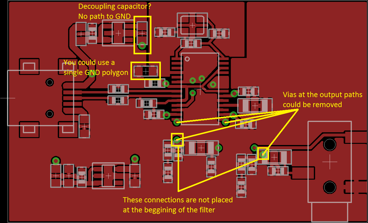
This is my layout, hope some one can help me to find out the problem.

  • Hi Thai,

    Welcome to e2e.
    I will take a look at your issue.
    I cannot see the files you have attached, could you upload your files again so I can take a look at them?
    Are you using PCM2704 in USB-powered or SELF-powered mode? Do you have captures of the supply rails and Vcom? (Just to make sure that these voltages are clean).

    Best regards,
    -Ivan Salazar
    Texas Instruments
  • Thanks for your help, here is the measurement using qa400:
    http://i.imgur.com/uj50hGR.png
    http://i.imgur.com/5Re0fa7.png
    And here is my layout:
    http://i.imgur.com/m37LQwQ.png
    http://i.imgur.com/9D4KASY.png
    I use it in self powered mode and power rail measure fine at 3.3V
  • Hi Thai,

    I added some notes to one of your design images.
    I'm concerned about the GND polygons. One has DGND and ZGND connected directly and the other has AGNDL, AGNDR and PGND. ZGND is ground for internal regulator and all the supply rails decoupling capacitors are connected to the other set of GND; besides PGND is ground for DAC, OSC and PLL and this is not connected directly to the crystal oscilator circuitry. It seems that both ground polygons are connected on a single point by a resistor or ferrite bead but maybe this connection is not strong enough to let the device work fine. Some times a bad ground connection causes noise issues.
    You could use the PCM2704C EVM design as reference.

    Best regards,
    -Ivan Salazar
    Texas Instruments

  • Hi Ivan, Thanks for your reply. The two parts in the top is ferrite bead, i isolate the digital ground to power supply by the ferrite bead, i tried shorting it but the problem is still remain. I want to seperate analog ground part and digital ground part. Each of them return to the regulator ground then back to the usb ground. " PGND is ground for DAC, OSC and PLL and this is not connected directly to the crystal oscilator circuitry" does this mean that PGND should be connected to the digital ground? Thanks!
  • Hi Thai,

    Yes PGND should be connected to digital ground.
    My concern about the component after the regulators is that one of them (the one on the top) is in series and the other one (the one on the bottom) is in parallel and connected to GND. Why is this difference?
    The connection to the output filter components may not be correct as this is not connected at the beginning of the filter.

    Best regards,
    -Ivan Salazar
    Texas Instruments