Because of the Thanksgiving holiday in the U.S., TI E2E™ design support forum responses may be delayed from November 25 through December 2. Thank you for your patience.

This thread has been locked.

If you have a related question, please click the "Ask a related question" button in the top right corner. The newly created question will be automatically linked to this question.

EMI/EMC Issues with TPA3116

Guru 15580 points

My TPA3116 design appears to have a significant radiated emissions problem, mostly from ~70MHz to ~160MHz. I have followed the TI design and layout guidance in the datasheet and EVM documents. I am amazed at the excellent results shown on page 22 of the TAP3116 datasheet. This design appears to have >20db of margin. Having spent way too much time on other projects trying to pass FCC certification testing, this plot was one of the reasons I chose the TPA3116. But my results are no where close to this.

Can I get a copy of this test report? I would like to compare my design and to see how this unit was tested. Are there photos of the test setup? Is this report available on the FCC website? Is there an FCC ID?

  • Hi, Mike

             Sorry,  I do not have the setup picture on my hand.

              1) I suppose the output filter you use  is LC filter (Inductor + capacitor).

              2) What is the output power? What is the load impedance?

     3) Could you share your schematic and layout to me?

    I will check the schematic to see if any help we can provide.

  • Peter,

    1) Can you give me the FCC ID for this test? Was the PA enabled when this scan was taken?

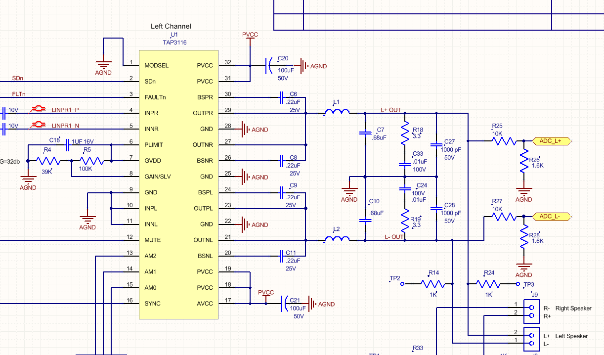
    2) The schematic of one of the output sections is shown below. There are two channels that are identical to this. This design is taken from the datasheet figure 37.

    2) The circuit shows excessive EMI with our without a load, with or without audio, irrespective of output power level.

    3) The layout of one of the channels is shown below. It is a 4-layer board. One layer of the board is dedicated to PVCC. Another layer of the board is dedicated to analog ground.

    4) The spectrum scan below shows (blue) PA disabled, (yellow) PA enabled, not output load, no audio. Marker #1 is at ~65MHz and Marker #2 is at ~135MHz.

    Has anyone been able to pass FCC part 15 subpart B unintentional radiated emissions testing with this part?

  • Hi, Mike

           Have you tried adding snubbers before LC filter (next to device)?