This thread has been locked.

If you have a related question, please click the "Ask a related question" button in the top right corner. The newly created question will be automatically linked to this question.

PCM1865 "Mix & Mux" in Page 19 of Datasheet Clarification

Other Parts Discussed in Thread: PCM1865

Hello,

I have a question about the PCM1865.

Question References

 - On Page 18. Figure 19. There is a dotted line that shows 2 more ADCs. I'm assuming these are the two extra ADCs found in the 1865 (as opposed to the other 186x chips). But it DOES NOT reference an additional 2 "Mix and MUX" sections. 

 - On Page Figure 20. There is a drawling of the Analog front end. But it does not show 4 ADCs, only 2.

 - On page 19 under section 8.5 that  "The Mix and MUX circuits are summing circuits, done pre-PGA. No individual volume controls are available before the PGA." 

Questions

 -  The PCM1865 has 4 ADC sections. Does it ALSO have 4 MIX and MUX sections??

 -  Does the PCM1865 have 4 PGA's or just 2 PGA's?

This is what I need. 

 - VINL1 + VINL2 -> MIX AND MUX 1 --> ANALOG PGA > ADC 1 -> DIGITAL PGA

 - VINR1 + VINR2 -> MIX AND MUX 2 -> ANALOG PGA -> ADC 2 -> DIGITAL PGA

 - VINL3 + VINL4 -> MIX AND MUX 3 -> ANALOG PGA -> ADC 3 -> DIGITAL PGA

 - VINR3 + VINR4 -> MIX AND MUX 4 -> ANALOG PGA -> ADC 4 -> DIGITAL PGA

Jay

  • I also reference Figure 37 on Page 41. This diagram does not show me what the 4 ADC channels will look like

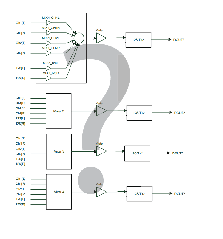
    Here is the diagram:

    Here is what I need... Is this the PCM1865 or no?

    I fear that the answer is that the PGA1865 has 2 ADCs for the stereo pairs and then 2 more for the GPIO headers.... :-( The more I read the more I think that's the case. Which means no individual control over microphones. Can someone confirm?

  • I would also like to point to the image on Page 19. It DOES NOT show 4 mixers.... It only shows 2. But it has the dotted lines for the ADCs. Either the data sheet is incorrect, or the chip is designed really oddly. I don't know why you'd want two channels of the exact same mix.

  • Hi Jay,

    Sorry about the confusion. The best way to look at it is by looking at the register map. For each ADC, you have the option of any of the available mixs, meaning 4 independent choices or 4 mux/mix blocks (for 4 channel devices).

    As for the DOUT and DOUT2 question, each DOUT is an I2S output, meaning 2 channels of audio per output pin. Therefore only 2 output pins are necessary for 4 channels. There is also the option of doing a TDM output, where you can have all 4 main ADC outputs on one data line.

    Justin