This thread has been locked.

If you have a related question, please click the "Ask a related question" button in the top right corner. The newly created question will be automatically linked to this question.

Audio Codec with loopback included

Other Parts Discussed in Thread: TLV320AIC34, TLV320AIC3204, TLV320AIC3254, TLV320AIC3254EVM-K

Hello,

We've recently developed a product using AIC34 Codec.

The main issue we faced during product Bring Up stages was the lack of loopback on board.

We are now designing the next product, and for that, we would like to have a similar capability Codec, but with loopback included.

Can anyone from the respected forum recommend on such device?

Thanks!

  • Hi, Tzviel,

    Can you please provide more information about the specs of the codec you are looking for?, we have several coded options with loopback capability, so having more information would be useful for us to suggest the better solution. 

    Thanks and Regards,

      -Diego Meléndez López
       Audio Applications Engineer

  • Hello Diego, thank you for replying.

    I think a best reference will be to point you on our previous TI product, TLV320AIC34.
    From technical point of view, this product abilities are sufficient, so the future product should meet the same requirements (in terms of number of channels, configurations, DAC and ADC abilities and so on).

    Basically, having the same product, but with loopback included will be excellent.

    Feel free to ask more specific questions, if needed.

    Thanks,
  • Hi, Tzviel,

    Thanks for the reference. It would be complicated to recommend the same solution as the TLV320AIC34 as we don't have a device similar in terms of number of inputs, outputs and channels. We have different codecs like the TLV320AIC3254 ot TLV320AIC3204, which performance is better, offer best processing options and have loopback capability,  but have less inputs and outputs than the AIC34.

    Best Regards,

       -Diego Meléndez López
      Audio Applications Engineer

  • Thank you Diego,

    I have looked on these suggested Codecs, and have a few questions for you:

    1. It seems that each of them only have 1 input channel (can be set to differential) - is that correct?

    For my use case, I need to have at least two input channels, connected to USB entry in PC. In AIC340, I could easily do that using the USB-MODEM EVB - Is there a similar method for these boards as well?

    2. Configuration interface - Is configuration of these codecs done in the same manner as for AIC340? Using I2C writes through dedicated tool?

    Regards,

    Tzviel

  • Hi, Tzviel,

    1. The TLV320AIC32x4 has two channels (left/right ADC). These channels have one input that can be configured in single-ended and differential modes. It is possible to route all the analog inputs (INx_L/R) to the mixers. Please take a look at the block diagram for details:

    Additionally, the USB MODEVM board can be used in similar way. Actually, our TLV320AIC32x4EVM-K uses this INTERFACE board to work correctly. This board provides the I2S clock signals to the codec ( http://www.ti.com/lit/ug/slau266a/slau266a.pdf.

    2. These devices can be configured via I2C and SPI. There's a pin called SPI_SELECT which is used to select the desired protocol. The registers are written by the selected protocol.

    Best regards,
    Luis Fernando Rodríguez S.

  • Hi Luis,

    Thank you for the explenation.

    Can you please clarify one point -

    Where can I find the LoopBack from the output line? This was my original requirement for this board, but I cannot see it in the schematics.

    Thanks,

  • Hi, Tzviel,

    The TLV320AIC32x4 support digital loopback (ADC output to DAC input) which can be configured with Page 0 / Register 29 / Bit D4. This function is not marked in the block diagram. It routes the left/right ADC output to the left/right DAC input.

    If you are looking to route the DAC output to ADC input, this function only can be made by the TLV320AIC3254 since it has internal miniDSP. The miniDSP offers more capabilities than the processing block of both devices, so there are more functions that it can make.

    Please let me know if you have more questions or comments.

    Best regards,
    Luis Fernando Rodríguez S.
  • Hi Luis,
    what we want to do with the loopback capability is to play a stereo sound and record a stereo sound simultaneously
    and we want to be able to remove the played sound from our recording.

    if i understood your solution correctly we must use 1 ADC and 1 DAC for the loop back feature meaning we have only 1 ADC and 1 DAC left for playing and recording so if loop back feature is enabled we can play and record only a MONO sound
    am i right?
    if yes is there a board the can support what we are trying to do?

    Thanks
  • Hi, Guy,

    Almost all of our codecs can record and playback simultaneously. The I2S interface is full-duplex. So, our codecs can record a sound and playback it from I2S or analog input (it would depend of your internal configuration). So, this function can be made even with both ADCs and both DACs. It can be a stereo solution. However, if you are looking to remove the played sound from the recording, you should need additional devices for AEC (acoustic echo cancellation). Please see the following wiki article for details: e2e.ti.com/.../2521.minidsp-echo-cancellation-aec

    Please let me know if you have more questions or comments.

    Best regards,
    Luis Fernando Rodríguez S.
  • hi luis

    we bought the AIC3254 board and we have a couple of questions:

    1. default board recording configuration:

    1. on board mic - we were able to record using on board mic default script configuration.
        also when disconnecting W2,W3 and connecting external mic and using same configuration record path worked
       but when trying to run High Performance Stereo Recording using IN1 and connecting external mic to IN1 record path didn't work.
       we also tried running the same onboard mic configuration (modified for external mic) and it still didn't work.
      

    2. we were able to enable loop back - meaning record sound directly from PC and play it , but we couldn't find a configuration that allow us to subtract between the loop back signal and the recorded one (we were expecting to record silence actually)

    can you please advise on both issues?

    see attached script.

    Thanks,

    Tzviel 

    --------------------------------------------------------

    ###############################################
    # On-Board Differential Microphone
    # ---------------------------------------------
    # PowerTune mode PTM_R4 is used for high
    # performance 16-bit audio.
    #
    # For normal USB Audio, no hardware change
    # is required.
    #
    # If using an external interface, SW2.4 and
    # SW2.5 of the USB-ModEVM must be set to
    # HI and clocks can be connected to J14 of
    # the USB-ModEVM.
    #
    # IN3L/R is are routed differentially to the
    # LADC.
    ###############################################

    ###############################################
    # Software Reset
    ###############################################
    #
    # Select Page 0
    w 30 00 00
    #
    # Initialize the device through software reset
    w 30 01 01
    #
    ###############################################

    ###############################################
    # Clock Settings
    # ---------------------------------------------
    # The codec receives: MCLK = 11.2896 MHz,
    # BLCK = 2.8224 MHz, WCLK = 44.1 kHz
    ###############################################
    #
    # Select Page 0
    w 30 00 00
    #
    # NADC = 1, MADC = 2
    w 30 12 81 82
    #
    ###############################################

    ###############################################
    # Signal Processing Settings
    ###############################################
    #
    # Select Page 0
    w 30 00 00
    #
    # Set the ADC Mode to PRB_P1
    w 30 3d 01
    #
    ###############################################

    ###############################################
    # Initialize Codec
    ###############################################
    #
    # Select Page 1
    w 30 00 01
    #
    # Disable weak AVDD in presence of external
    # AVDD supply
    w 30 01 08
    #
    # Enable Master Analog Power Control
    w 30 02 00
    #
    # Select ADC PTM_R4
    w 30 3d 00
    #
    # Set the input powerup time to 3.1ms (for ADC)
    w 30 47 32
    #
    # Set the REF charging time to 40ms
    w 30 7b 01
    #
    ###############################################

    ###############################################
    # Recording Setup
    ###############################################
    #
    # Select Page 1
    w 30 00 01
    #
    # Powerup MIC BIAS
    w 30 33 40
    #
    # Route IN3L to LEFT_P with 10K input impedance
    w 30 34 04
    #
    # Route IN3R to LEFT_M with 10K input impedance
    w 30 36 04
    #
    # Unmute Left MICPGA
    w 30 3b 00
    #
    # Unmute Right MICPGA
    w 30 3c 00
    #
    # Select Page 0
    w 30 00 00
    #
    # Power up LADC/RADC
    w 30 51 c0
    #
    # Unmute LADC/RADC
    w 30 52 00
    #
    ###############################################


    -------------------------------------------------------------------------------------

    ###############################################
    # High Performance Stereo Recording
    # ---------------------------------------------
    # PowerTune mode PTM_R4 is used for high
    # performance 16-bit audio.
    #
    # For normal USB Audio, no hardware change
    # is required.
    #
    # If using an external interface, SW2.4 and
    # SW2.5 of the USB-ModEVM must be set to
    # HI and clocks can be connected to J14 of
    # the USB-ModEVM.
    #
    # IN1L/R is routed to the LADC/RADC in a
    # single-ended manner.
    ###############################################

    ###############################################
    # Software Reset
    ###############################################
    #
    # Select Page 0
    w 30 00 00
    #
    # Initialize the device through software reset
    w 30 01 01
    #
    ###############################################

    ###############################################
    # Clock Settings
    # ---------------------------------------------
    # The codec receives: MCLK = 11.2896 MHz,
    # BLCK = 2.8224 MHz, WCLK = 44.1 kHz
    ###############################################
    #
    # Select Page 0
    w 30 00 00
    #
    # NADC = 1, MADC = 2
    w 30 12 81 82
    #
    ###############################################

    ###############################################
    # Signal Processing Settings
    ###############################################
    #
    # Select Page 0
    w 30 00 00
    #
    # Set the ADC Mode to PRB_P1
    w 30 3d 01
    #
    ###############################################

    ###############################################
    # Initialize Codec
    ###############################################
    #
    # Select Page 1
    w 30 00 01
    #
    # Disable weak AVDD in presence of external
    # AVDD supply
    w 30 01 08
    #
    # Enable Master Analog Power Control
    w 30 02 00
    #
    # Select ADC PTM_R4
    w 30 3d 00
    #
    # Set the input powerup time to 3.1ms (for ADC)
    w 30 47 32
    #
    # Set the REF charging time to 40ms
    w 30 7b 01
    #
    ###############################################

    ###############################################
    # Recording Setup
    ###############################################
    #
    # Select Page 1
    w 30 00 01
    #
    # Route IN1L to LEFT_P with 20K input impedance
    w 30 34 c0
    #
    # Route Common Mode to LEFT_M with impedance of 20K
    w 30 36 80
    #
    # Route IN1R to RIGHT_P with input impedance of 20K
    w 30 37 80
    #
    # Route Common Mode to RIGHT_M with impedance of 20K
    w 30 39 80
    #
    # Unmute Left MICPGA, Gain selection of 6dB to make channel gain 0dB
    # Register of 6dB with input impedance of 20K => Channel Gain of 0dB
    w 30 3b 00
    #
    # Unmute Right MICPGA, Gain selection of 6dB to make channel gain 0dB
    # Register of 6dB with input impedance of 20K => Channel Gain of 0dB
    w 30 3c 00
    #
    # Select Page 0
    w 30 00 00
    #
    # Power up LADC/RADC
    w 30 51 c0
    #
    # Unmute LADC/RADC
    w 30 52 00
    #
    ###############################################

  • Hi, Tzviel,

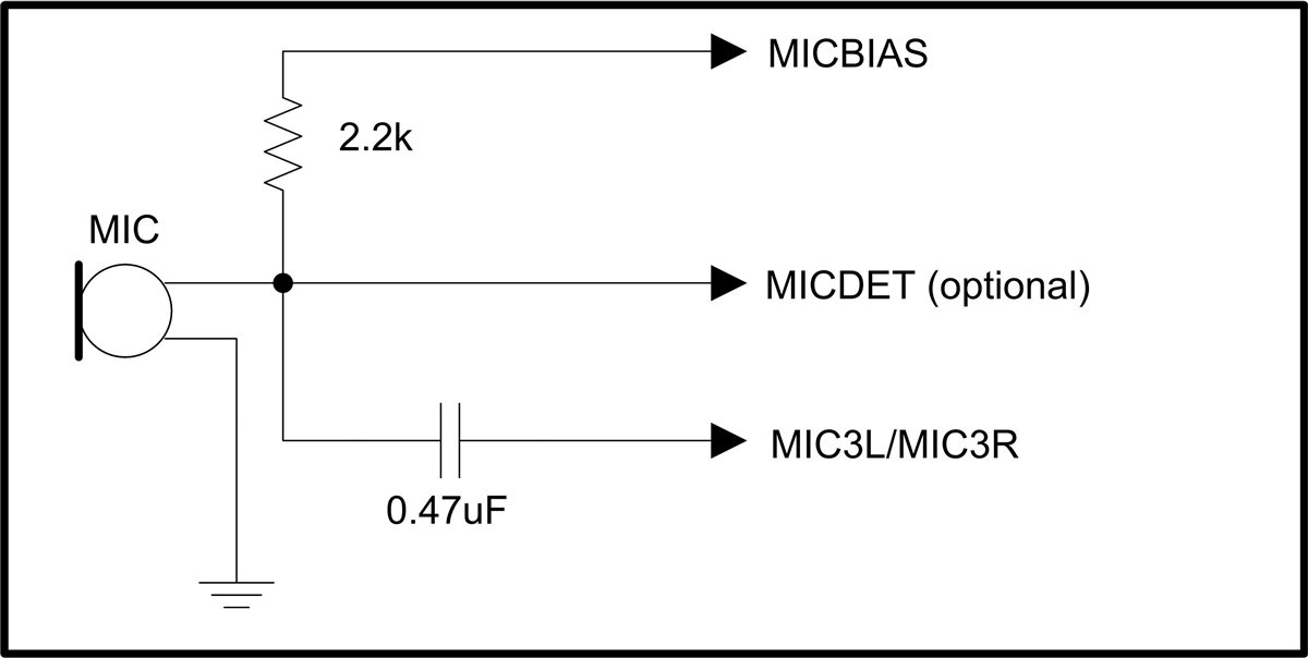
    1. The microphone configuration on the EVM (external or on-board) only can be used at the input IN3L/R. If you are looking to route the IN1L/R input to the microphone, then you should connect the MICBIAS pin to the microphone and enable it with in the register configuration:

    # Select Page 1
    w 30 00 01

    # Powerup MIC BIAS
    w 30 33 40

    2. If my understanding is correct, you are looking to substrate the ADC input (IN3L/R for example) from the I2S input (loopback signal). In this case, you would require to develop your algorithm in PurePath Studio. This tool is used with the TLV320AIC3254EVM-K for signal treatment. So, this would be helpful for your application. If you are interested in this software, you may request it in this link:

    http://www.ti.com/tool/aicpurepath_studio

    Best regards,
    Luis Fernando Rodríguez S.

  • Hi Luis,
    we are trying to follow AIC3254 Acoustic Echo Cancellation Application Note to implemented it in our board.
    We are using PurePath Studio version 5.95 build 1 revision 35815, with component Library Version 6738.

    we could not find in the PurePath studio the same Framework " AIC3254_AEC_Framework" as described in the AN. furthermore, there are no AEC component in the "component list".

    can you please advise how can we implement the AEC concept with our current version.
    thank you.
    Eyal
  • Hello, Eyal,

    Welcome to E2E and thank you for your interest in our products!

    Unfortunately, the Acoustic Echo Cancellation is not supported anymore since the miniDSP doesn't have enough capabilities to make a really effective AEC. Please take a look at this note for details:

    e2e.ti.com/.../2521.minidsp-echo-cancellation-aec

    Best regards,
    Luis Fernando Rodríguez S.
  • Hi Luis, Thank you for supporting us with this product development.

    You've mention in your posts that using AIC3254 we can record both Audio Loopback and Audio record **simultaneously**.

    So far we were able to:

    1. Enable Audio Loopback between DAC and ADC, so we could record back the played signal
    2. Enable Record and Playback path simultaneously

    However, we couldn't enable both options together. I will elaborate:

    Our main target is to play specific audio files, and record information simultaneously. Also, in order to run 'echo cancellation' algorithm on our recorded data, we need to capture Loopback path as well, and use it in our algorithm.

    Ideally, we would like to record stereo data as well loopback (3 channels of record), but we understand it might be a problem, so we can also dedicate one channel for record, and the other for Loopback.

    So far, we couldn't find a way to configure the board for this method, and we will appreciate if you can assist us with the desired configuration - 

    1. Setting Digital Loopback between DAC and ADC path
    2. Route it to Right ADC
    3. Route Audio record path to Left ADC simutlaneously

    Thank you in advance!

    Tzviel


  • Hi, Tzviel,

    The TLV320AIC3254 is able to make this loopback and record path by the usage of the miniDSP. The miniDSP can use an interprocessor option to work with miniDSP_A and miniDSP_D. So, I recommend to use PurePath Studio tool ( www.ti.com/.../aicpurepath_studio ) in order to create a specific process flow for your application.

    Best regards,
    Luis Fernando Rodríguez S.
  • Hello Luis,

    As you know, we are trying to build a configuration with the PurePath studio to route the DAC output to the ADC input.

    we need your help to understand which components should we use in order to set the Digital Loopback between DAC and ADC path, and how how can i choose which ADC the data will route?

    please advise,

    thank you

  • Hi, Eyal,

    The Digital loopback between DAC and ADC is made with an interprocessor block. This block communicates the digital side with the analog side. So, the DAC can be routed to the ADC. Please take a look at the following picture for details:

    The ADC input can be selected by the SystemSettings Code of the Properties window of the AIC3254 framework. This code contains the register information of the codec. So, you may select the inputs that you are going to use in your application.

    Best regards,
    Luis Fernando Rodríguez S.

  • hi Luis,

    we were able to configure loop back in the board - meaning we can hear an audio file using our headphones and record it in the same time

    as you can see : we connected I2S In R to MonoInt2xOut_1x , and using the DSP also to I2S out R

    we also want to record on the same time so we tried using : MonoDec4xAGCIn but we couldnt record anything

    we want to know how we can configure the input microphone to go to I2S I/F

    appreciate your help

    Thanks

  • Hi, Eyal,

    First of all, I recommend to replace the MonoDec4xAGCIn_ block by the MonoDec4xIn block. Then, I suggest to ensure that the correct analog input and MICBIAS are configured in the SystemSettingsCode as mentioned above.

    Best regards,
    Luis Fernando Rodríguez S.