This thread has been locked.

If you have a related question, please click the "Ask a related question" button in the top right corner. The newly created question will be automatically linked to this question.

TPA2005 Amp has VDD On Speaker Output. Why?

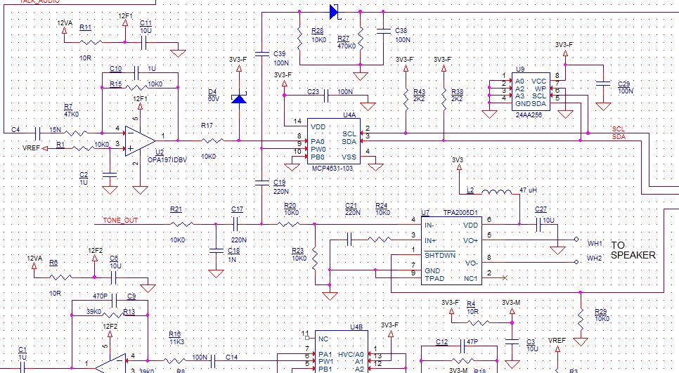
I have a new design using the TPA2005 class D audio amplifier. I've verified everything I can think of, but I still seem to be getting my VDD rail showing up directly across my speaker output. Can I safely assume that the FET's in the part must have gotten damaged somehow to cause this?

I'm looking for any insight how this could happen and what I might be doing wrong with my circuit. In the attached circuit I have already removed D4 since this will obviously cause problems with being forward biased all the time. I also realize the output of U2 should be AC coupled before going into U4 (digital POT). The audio going into the class D amp is ground referenced. L2 has also been removed since the inductive kick from this on power down could do it. I've replaced L2 with a ferrite instead, and replaced the TPA2005. Same DC level on amp output.

  • I think R23 is your problem. TPA2005 has a fully differential amplifier at the inputs with internal feedback resistors already in place. Capacitor C21 is acting as a DC blocking capacitor. If you had an equivalent configuration on IN- your inputs and outputs should bias to mid supply. Instead, you're creating your own DC bias for this input which forces your output to Vdd. Are you trying to attenuate the signal by 1/2? This might be better accomplished in conjunction with R21 instead of R20.
  • Thank you. I saw that as well and have removed R23 and I still get 3.3V across the output. Could the presence of R23 have damaged the part to the point where some form of latchup condition has been created? My next step is to replace the amp in case I've damaged it as a result of R23 being in place. I don't see any excessive current draw as a result of this issue at all. Idle current is still normal.
    The original intent was to attenuate the signal further as you mention with R23 for one of two audio sources. One will get attenuated by the digital POT without a problem, but the other is a microcontroller pin that gets filtered. I need to move that attenuation prior to the summing node and then do the summing properly like the datasheet shows.
  • Hello Byron,

    Welcome to E2E, thanks for your interest in our products.
    Have you tried to use the device without inductor? In this way you could discard that possibility.
    Could you please provide me more details like the load value and input signal level?

    Best Regards
    Jose Luis Figueroa
    Audio Applications Engineer | A-Team
  • What DC voltages do you see at your inputs with R23 removed?
  • I see 0V on each of my inputs which is definitely a problem. I have an eval board here as well and I can see the input pins on it are measuring 1.5V or 1/2 my VCC rail which makes sense. It's looking like I've damaged the part, but I wasn't sure if the presence of R23 alone would be enough to cause that.
  • I noticed as well that the use of L2 is a bad idea because of the spike this will cause at the VDD pin of the amp when power is removed. This quite likely will exceed VDD max. I have since replaced it with a ferrite, replaced the amp and the problem persisted with 3.3 on the speaker output. I did this before doing anything with the removal of R23 so maybe this was contributing to the problem. Since I don't see the 1.5V bias on the inputs the way I should, it looks like I have damaged this part as well.
  • Byron,

    After of you replace the damaged device, you could try to use the device without inductor and R23 in order to discard some problem with them.
    Which is the load value?

    Best Regards
    Jose Luis Figueroa
    Audio Applications Engineer | A-Team
  • This morning I have replaced the amp. I have made sure that inductor L2 is replaced by a ferrite, and R23 is removed. With nothing connected to pin 3 and 4 of the amp, I powered it up and measured the DC level sitting on 3 and 4 with respect to ground. I measure 1.5V on each as expected. I measured the output on 5&8 and measured 0 V DC.
    Next I connected my input resistors and capacitors but with no audio input signal. Once again I measured pins 3 & 4 and they still have 1.5V on each and still no DC showing up on my speaker output. All good so far.
    I connected my signal generator with what I thought was a very small input signal to my single ended input going into pin 4. I measured pins 3 & 4 and the 1.5V is still there, but now I get 1.67V showing up on my output at pins 5&8. I checked my input signal level which I thought was low and found I had it at 0.7 VAC. Could I have over driven the input and damaged the amp again even though I had no speaker load applied (pins 5 & 8 where open circuit)?
    I have been using 10K and 1N as my input values. I see now on page 4 that the minimum input resistor value should be 15K. Could this have contributed to the problem as well?
  • After reviewing the datasheet more on how the gain works, I see now by the 10K that I had was far to small. I'll replace the amp (again) and bump this up to 150K for now so I have a gain of 1. I'll then feed in a much smaller input signal and I should be back in business.
  • Sounds good. Let us know how it turns out.
  • Everything working well now. Speaker is producing my tones properly. Thanks for all the input!! Greatly appreciated.