This thread has been locked.

If you have a related question, please click the "Ask a related question" button in the top right corner. The newly created question will be automatically linked to this question.

GND connections in an Audio Amplifier using a transformer with two secondary windings

Hi to everyone

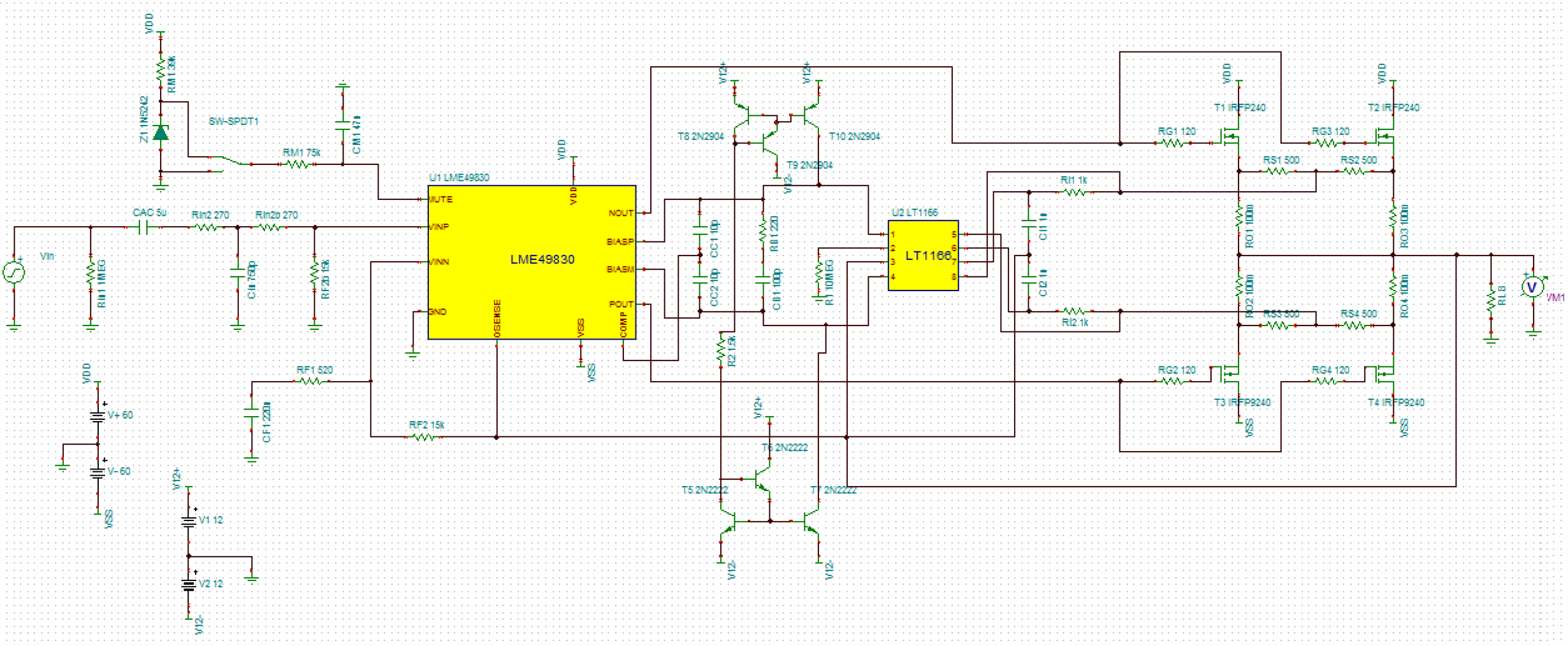
Currently I am building a MOSFET Audio amplifier based on LME49830 chip from TI. The scheme consists:


My power supply contains 2 PSU, the first one delivering +-60V to the POWER AMPLIFIER BOARD and the second one supplying +-12V to the PRE-AMPLIFIER board. In order to accomplish this, I ordered a costumed Transformer made for my requirements which consists on one primary winding and two secondary windings each one with a center tap (or mid-point, the GREEN one and the BLUE one).

This is the POWER AMP BOARD SCHEMATIC:

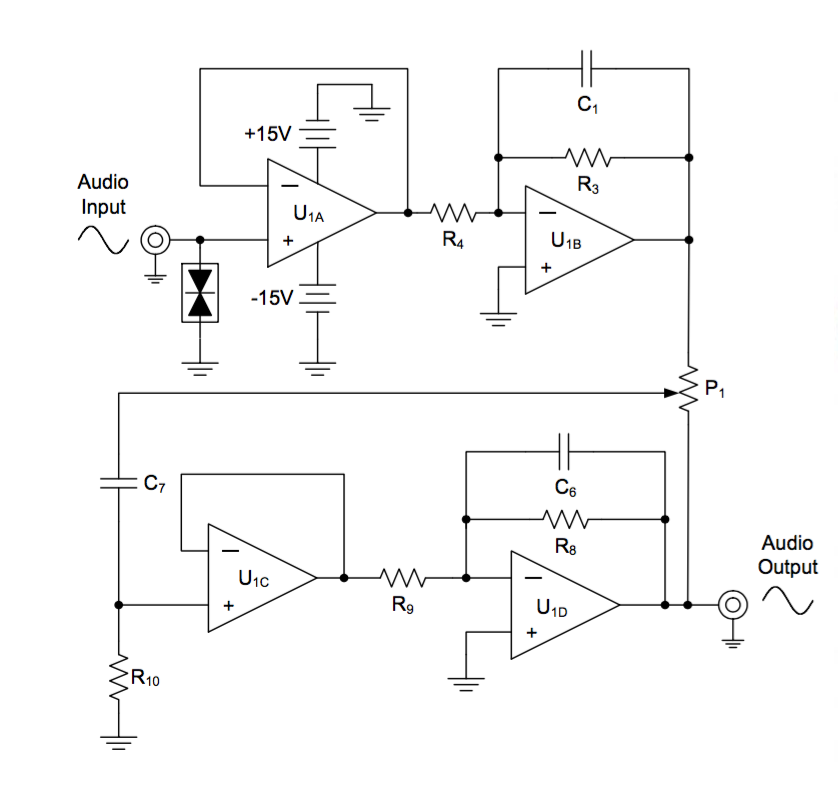
and this is the PRE AMP BOARD SCHEMATIC:

The problem is that these mid-points are in different potential so I don't know if I can just connect them.

My POWER AMPLIFIER board also needs the +-12V supply in order to supply a current mirror I am using for a chip.

How would GND connections be in this case? I am asking because the output of the PRE-AMP board is referenced to the center tap of the 2nd secondary winding (+-12V) and this output goes to the POWER AMP board which GND is the center tap of the 1st secondary winding.

The potential between the two center taps is about 7Vrms (I measured it with a multimeter).

My idea is to use a very low resistor (and high power) between these 2 center taps but I also want to use a GND star configuration in order to avoid GND loops.

I'll appreciate any help from you guys.

  • Hello Matias

    I think that two center taps shouldn't be connected between themselves because they have different potential.
    Have you tried to use the circuit without connecting the center taps together? if so, How is working the circuit?

    Best Regards
    Jose Luis Figueroa
    Audio Applications Engineer | A-Team
  • Hello Jose Luis

    Thanks for your answer. I think the same way, that is why I had the idea to use a resistor between those two grounds but no idea where to place it exactly.

    I haven't tried that yet, but I'll do that soon. Is there any chance that your proposal work? because at the input stage of the main power amplifier the signal would be referenced to the second ground (the blue one, of the second secondary winding) coming from the pre-amplifier and the signal at the output would be referenced to the first ground (the green one, of the first secondary winding).

    I don't know if we can assure that the currents at the input transconductance stage of the LME49830 chip would be the same whether the signal is referenced to the first ground or second ground at the input filter of the power amplifier circuit. I think that if we can assure that, there would be no problem to use your solution.

    Best Regards,

    Matías Henríquez

  • Matias,

    You are right, we can't assure that these circuits have the same current and that could be a problem. As you mentioned, You could connect them with a very low resistor, maybe that could resolve the problem.
    Please let me know if your solution works.

    Best Regards
    Jose Luis Figueroa
    Audio Applications Engineer | A-Team