This thread has been locked.

If you have a related question, please click the "Ask a related question" button in the top right corner. The newly created question will be automatically linked to this question.

PCM5122EVM-U Usage Help

Other Parts Discussed in Thread: PCM5122EVM-U, PCM5122

Hello,

I am trying to get the a PCM5122EVM-U board working. So far, I have gotten the driver installed and working on my PC. I was able
to load the "USB-AudioEVM0354_441KHZ.BIN" file onto the board. The switches and jumper are such that I2C mode selected, MCLK #3 (22.5792MHz)
is selected and W5 is selected so that the raw MCLK (oscillator) and not RXCKO output is routed to the PCM5122. I am playing audio on my PC
and have selected the device in my audio playback devices as the one to use for audio output.


What I want is to use the USB to stream audio to the board. I am checking a few things on the board, but I do not see a negative supply
voltage on the PCM5122 implying that the charge is not working. And I do not see any edges on LRCLK, DIN, or OUTL or OUTR. I do see D1
light up when connecting USB to the board, I see a 3.3V supply voltage and I see a valid MCLK but that is it.

Do I need to use Purepath to control some registers?

Need some guidance here.

  • Daniel,
    You can achieve USB input to stream audio to the board using Purepath studio GDE along w. setting the SW3 (A,B,C) to LOW. Please refer to section 3.1 in the below linked App note.
    www.ti.com/.../slaa541.pdf

    Please let me know if you need additional information.
  • So, there is no way to stream USB audio without PurePath Studio? If so, how do I get this software tool? I saw on its webpage
    that one has to request it. Is that right?

    I understand that PurePath downloads an image. Is this downloading the firmware that runs on the TAS1020? Can I not use
    one of the images provided in the TAS1020 firmware download to do the same thing?

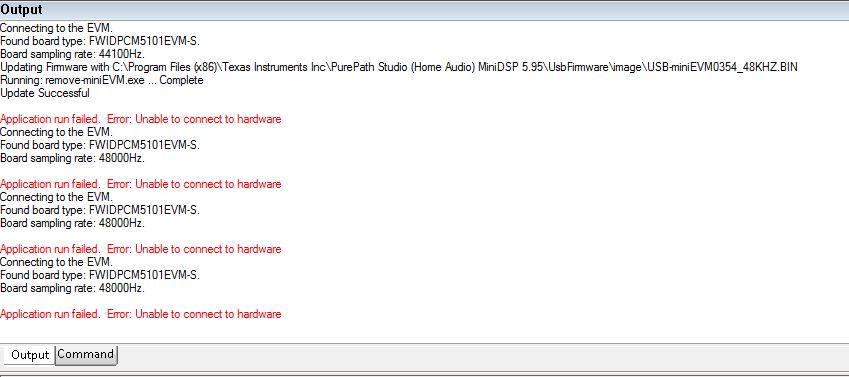
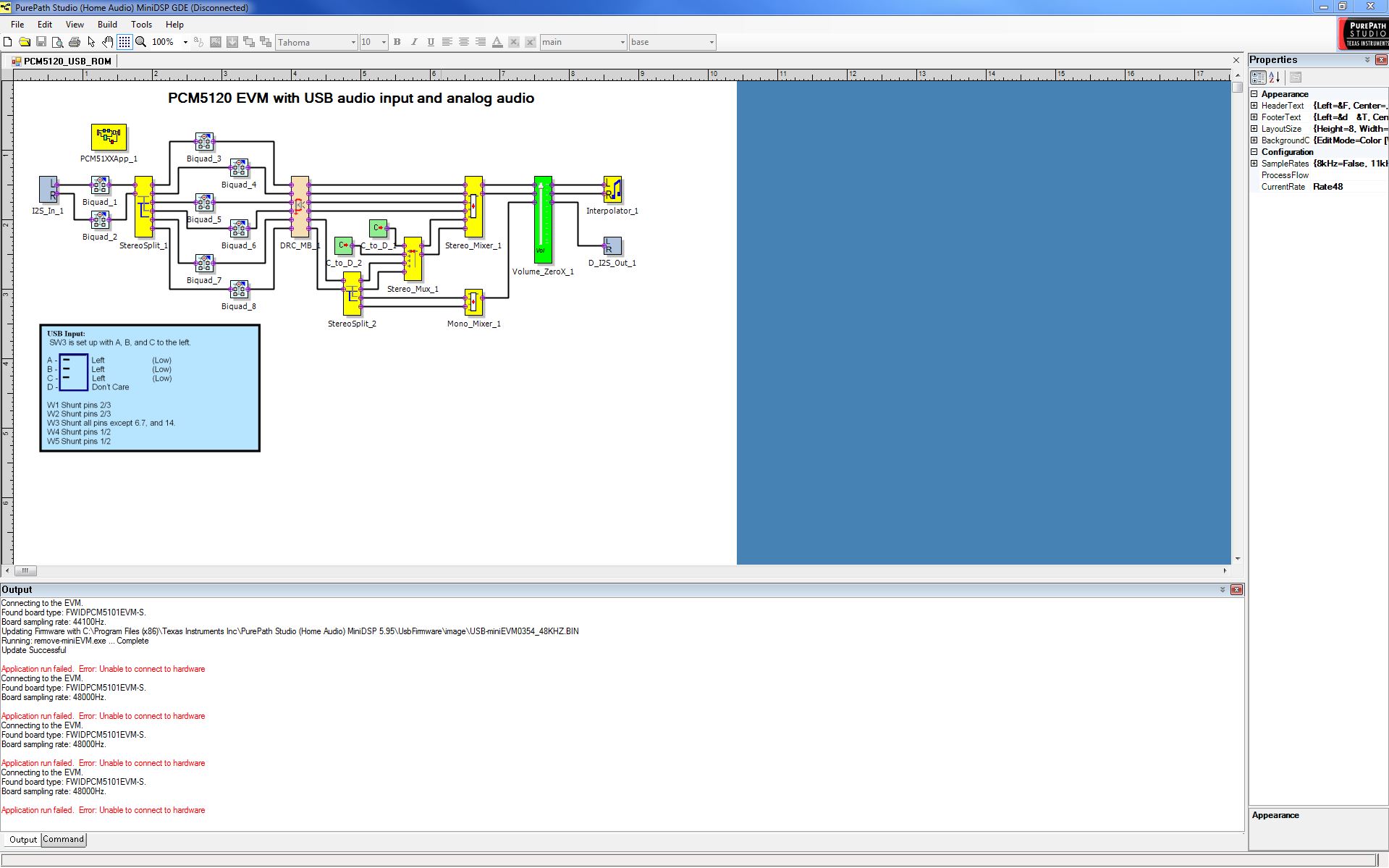
  • I downloaded PurePath Studio Home and installed it. I was able to connect to the EVM enough to update the firmware to 48kHz sampling rate. But I now have connection issues, see attached captures of the errors. I have the jumpers all configured as instructed per manual http://www.ti.com/lit/an/slaa541/slaa541.pdf

    Not sure if I understand the instructions for W3: W3 Shunt all pins except 6.7, and 14.

    Does this translate to except 5 to 6, 7 to 8 and 14-16? In my case, I have all shunts loaded except for pins 13-14. 
    Bottom line, is the PCM5122 supposed to be in I2C mode or hardware mode?

  • Ravi,

    Never mind my earlier responses. I figured out the correct set of jumpers. I had to set the address pins of the PCM5122 to GND in order for the I2C to connect to the PCM5122. I see a -3.3V power rail and data on the I2S bus now.