This thread has been locked.

If you have a related question, please click the "Ask a related question" button in the top right corner. The newly created question will be automatically linked to this question.

DC Offset at the output of TPA2100

Other Parts Discussed in Thread: LM48560

Hello

We are currently planning to use the TPA2100 Amplifier for a project together with a big customer. We have planned to use the amplifier to drive a piezo speaker which requires a positive voltage at the speaker. Therefore we have added a DC offset to the output of the amplifier (R18 and R19 inside the attached PDF). 

We now see a lot of noise at the output signal to the speaker and also the sound quality is very poor (SPL and THD are ok). Would it be possible to get support from TI to improve the circuit performance or to review our current circuit if this could cause problems within the amplifier?

Thank you and best regards

Markus

TPA2100.pdf

  • Hi

    Welcome to E2E, thanks for your interest in our product.
    I'm going to work in this matter and I'll be responding soon with further information.

    Best Regards
    Jose Luis Figueroa
    Audio Applications Engineer | LPAA
  • Hello,

    You are adding a DC offset to the amplifier's output and that isn't necessary, the common-mode feedback on this device ensures that the common-mode voltage at the output is biased around Vdd/2 regardless the common-mode voltage at the input, therefore the device wouldn't get any negative voltage. I think that the DC offset is caused these issues, you should remove R18 and R19. The output capacitors aren't necessary either.

    Best Regards
    Jose Luis Figueroa
    Audio Applications Engineer | LPAA
  • Hello

    Thank you very much for your reply. Yes this is true that the common mode voltage on the outputs is at around vdd/2. So assuming a 10V boosted output, this means that the output signal at the positiv and negativ output is in the range of 0 V to 10 V (measured to gnd). This means that the voltage on both pins of our speaker can be in the range of 0V to 10 V, measured to ground.  Nevertheless the voltage between both of those pins (from our speaker) can no go from -10V to 10V. This is also the reason why you can reach up to 19Vpp. Can you confirm this?

    This is basically the reason why we still need the DC offset (and the capacitors to block this DC offset from the output of the amplifier). We are not allowed to have a voltage of -10V to 10V at the speaker terminals. If we add know a DC offset of 10V this results in around 0V to 20V between both speaker terminal.

    If possible we could also have a short call to discuss the problem in details and give you more information.

    Thank you and best regards

    Markus Haensler

  • Hello Markus,

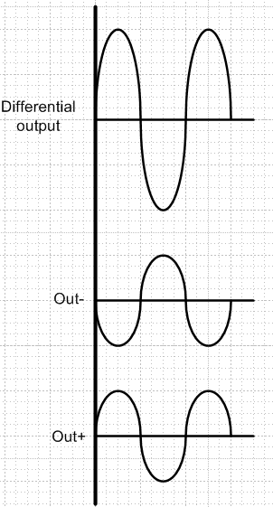
    For instance, as you have mentioned,  the output signal at Output + and Output - is in the range of 0V to 10V, but this device includes a differential amplifier with common-mode feedback, that means that the differential output(from the speaker) is equal to the differential input times the gain, it means 0V to 20V without DC offset. Below you can find a figure where is showed the output operation.

    As I mentioned you, You don't need DC offset. The common-mode feedback on this device ensures that the common-mode voltage at the output is biased around Vdd/2 regardless the common-mode voltage at the input, therefore the device wouldn't get any negative voltage. You could refer the Fully Differential Class-D Audio Power Amplifier section of the amplifier's datasheet to find further information.

    Please let me know your comments or if you need to have a short call.

    Best Regards
    Jose Luis Figueroa
    Audio Applications Engineer | LPAA

  • Hello

    Thank you very much for your answer and explanations. I fully agree on your explanations about the differential signal. Our problem is basically only the change of the polarity at the speaker. We are also currently looking at the LM48560. So it would be great if we could have a short call to discuss out application to see which circuit would fit best.

    Thank you and best regards

    Markus